Stainless Steel Slip-On Flanges - ISO/CE Certified
Sunhy supplies a complete range of Stainless Steel Slip-On (SO) Flanges, designed to slide over the pipe for straightforward alignment before being welded (fillet welds) on both the inside and outside.
We manufacture and stock flanges strictly to ANSI/ASME B16.5 standards, covering all pressure ratings from Class 150 to Class 2500. Our inventory includes both Raised Face (RF) and Flat Face (FF) options in common materials like SS304/304L and SS316/316L, ready for immediate dispatch for your project needs.
Types of Slip-On Flanges We Supply
 Stainless Steel Flanges
By Design Type
By Standard & Class
Advanced Materials
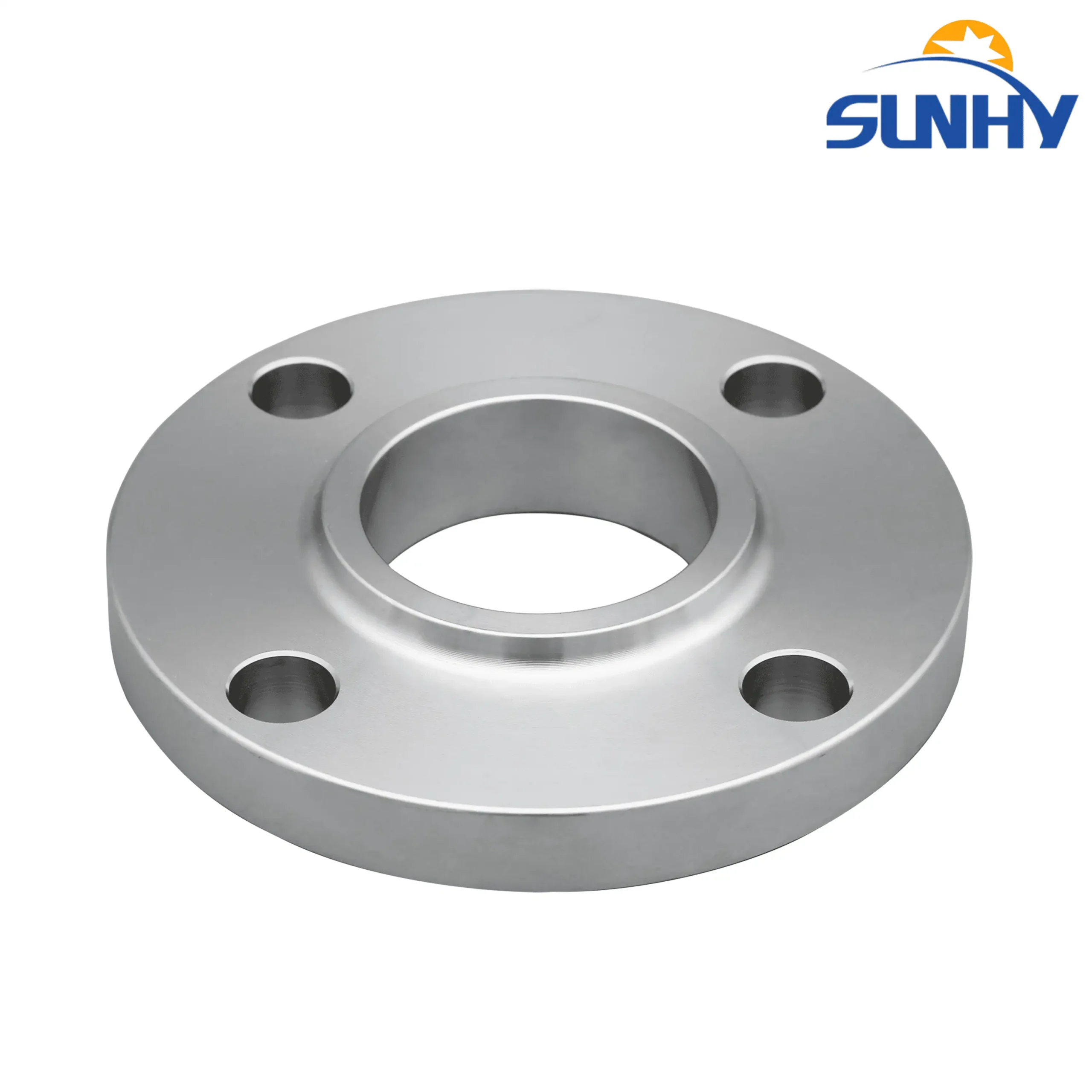
4-Bolt Stainless Steel Slip-On Flange, Flat Face (FF)
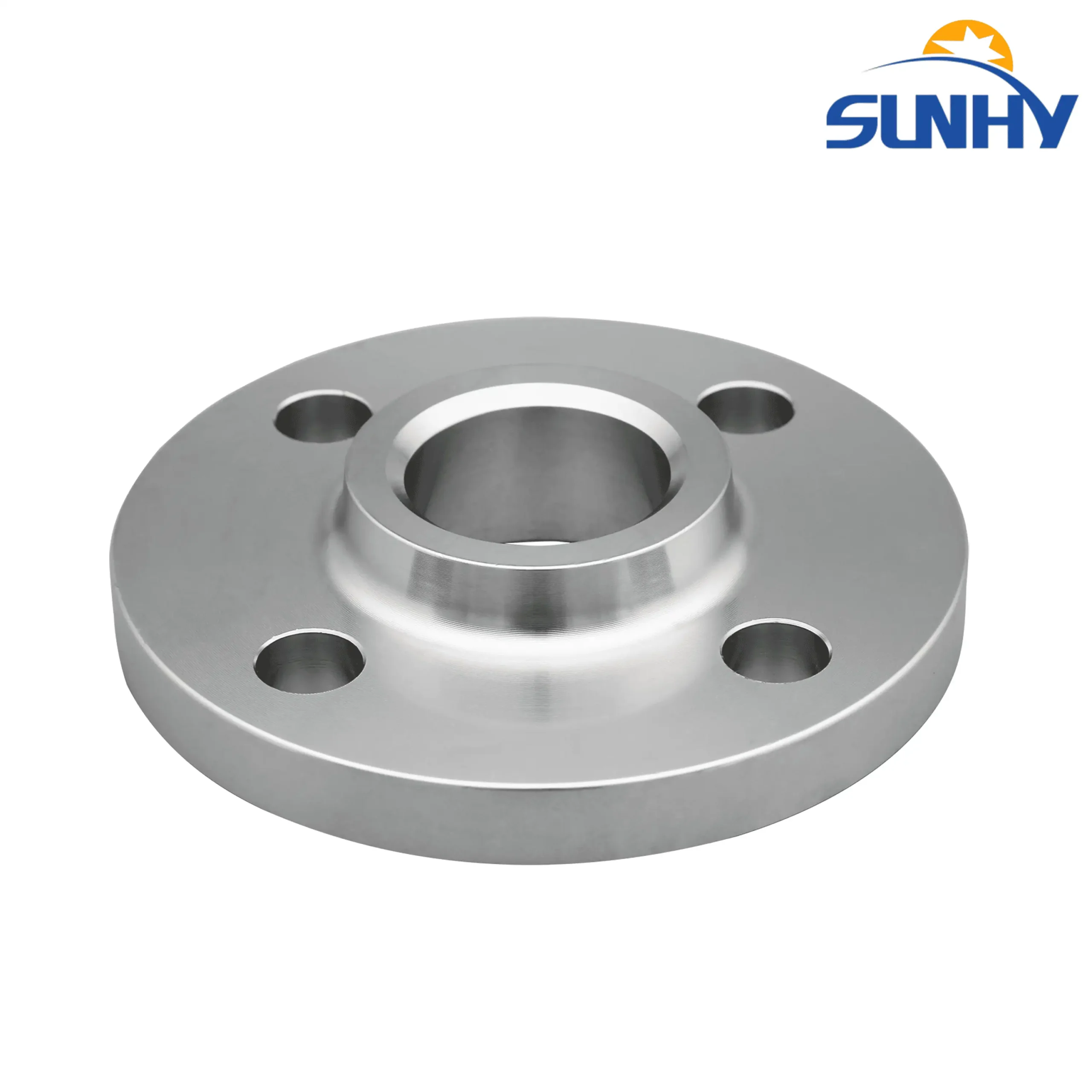
4-Bolt Stainless Steel Slip-On Flange, Raised Face (RF)
Why Choose Sunhy Slip-On Flanges ?
Real Manufacturing Capabilities: “We are not a trading company. Sunhy has 100 high-precision CNC machine tools to ensure that the surface finish (Ra) and dimensional tolerances of the sealing surfaces of every flange strictly comply with ASME B16.5 (or EN 1092-1) standards.”
Strict material control: “We use 100% stainless steel raw materials from major manufacturers such as Tsingshan Holding. All raw materials undergo composition testing using a handheld spectrometer (PMI) before entering the warehouse to eliminate unqualified materials.”
Clear Product Traceability: “Every Sunhy flange shipped bears a clear steel stamp containing: material (e.g., F316/F316L), pressure rating (e.g., 150LB), standard (e.g., ASME B16.5), size (e.g., 2), and a unique heat number, ensuring complete traceability.”
Delivery and Service: “We maintain a full range of standard sliding flanges in stock and can ship within 3 days. For your customized needs, our engineering team will provide one-on-one service.”
What is a Slip-On Flange?
“A slip-on (SO) flange is a type of pipe flange distinguished by its installation method: it is designed to ‘slip on’ or slide over the end of a pipe.
The inner diameter (or bore) of a slip-on flange is slightly larger than the pipe’s outer diameter. This design allows for easy positioning and alignment before it is secured in place. Installation is completed by applying two fillet welds: one on the outside (at the hub) and one on the inside of the flange.
Key Characteristics:
Installation: Generally easier and faster to align than weld neck flanges.
Cost-Effective: They are often lower in cost and fabrication labor.
Facing vs. Type (Important Distinction): ‘Slip-on’ refers to the flange type (how it attaches to the pipe). This should not be confused with the flange facing (the sealing surface). A slip-on flange can be supplied with a Raised Face (RF), Flat Face (FF), or Ring-Type Joint (RTJ) face, depending on the sealing requirements.”

Slip On Flanges (SO) Specifications
Global Standard Compliance
Our Slip On flanges are engineered for universal compatibility, strictly adhering to ASME B16.5 (Class 150-2500), DIN/EN 1092-1 (PN6-PN40), and JIS B2220 (5K-20K) standards. This multi-standard compliance ensures seamless integration into diverse piping systems across US, European, and Asian markets.
Material & Engineering Advantages
Available in high-precision Carbon, Stainless, and Alloy Steel to suit specific pressure and corrosion requirements.
-
Ease of Installation: The design allows the flange to “slip over” the pipe, accommodating slight variations in pipe length and simplifying alignment before welding.
-
Structural Integrity: Designed for dual fillet welding (internal and external) to ensure a secure, leak-proof joint.
Dimensional Reference
Refer to the cross-section diagram and table headers for key measurements:
-
O / D: Outside Diameter
-
BC / K: Bolt Circle Diameter
-
T / C: Flange Thickness
-
H: Overall Length through Hub
Technical Note: Slip On flanges require fillet welds on both the ID and OD. Ensure sufficient pipe insertion depth to prevent damage to the flange face during welding.

Slip On Flange (SO) Dimensions
Unit: Millimeters (mm)ASME B16.5 Class 150 - Full Standard Range
| NPS (Size) |
Outside Dia (O) (mm) |
Bolt Circle (BC) (mm) |
No. of Holes (Qty) |
Hole Dia (mm) |
Bolt Size (Inch) |
Thickness (T) (mm) |
|---|---|---|---|---|---|---|
| 1/2" | 88.9 | 60.5 | 4 | 15.7 | 1/2" | 11.2 |
| 3/4" | 98.6 | 69.9 | 4 | 15.7 | 1/2" | 12.7 |
| 1" | 108.0 | 79.2 | 4 | 15.7 | 1/2" | 14.2 |
| 1-1/2" | 127.0 | 98.6 | 4 | 15.7 | 1/2" | 17.5 |
| 2" | 152.4 | 120.7 | 4 | 19.1 | 5/8" | 19.1 |
| 3" | 190.5 | 152.4 | 4 | 19.1 | 5/8" | 23.9 |
| 4" | 228.6 | 190.5 | 8 | 19.1 | 5/8" | 23.9 |
| 6" | 279.4 | 241.3 | 8 | 22.4 | 3/4" | 25.4 |
| 8" | 342.9 | 298.5 | 8 | 22.4 | 3/4" | 28.4 |
| 10" | 406.4 | 362.0 | 12 | 25.4 | 7/8" | 30.2 |
| 12" | 482.6 | 431.8 | 12 | 25.4 | 7/8" | 31.8 |
| 14" | 533.4 | 476.3 | 12 | 28.4 | 1" | 35.1 |
| 16" | 596.9 | 539.8 | 16 | 28.4 | 1" | 36.6 |
| 20" | 698.5 | 635.0 | 20 | 31.8 | 1-1/8" | 42.9 |
| 24" | 812.8 | 749.3 | 20 | 34.9 | 1-1/4" | 47.8 |
ASME B16.5 Class 300 - Medium Pressure
| NPS (Size) |
Outside Dia (O) (mm) |
Bolt Circle (BC) (mm) |
No. of Holes (Qty) |
Hole Dia (mm) |
Bolt Size (Inch) |
Thickness (T) (mm) |
|---|---|---|---|---|---|---|
| 1/2" | 95.3 | 66.5 | 4 | 15.7 | 1/2" | 14.2 |
| 3/4" | 117.3 | 82.6 | 4 | 19.1 | 5/8" | 15.7 |
| 1" | 124.0 | 88.9 | 4 | 19.1 | 5/8" | 17.5 |
| 1-1/2" | 155.4 | 114.3 | 4 | 22.4 | 3/4" | 20.6 |
| 2" | 165.1 | 127.0 | 8 | 19.1 | 5/8" | 22.4 |
| 3" | 209.6 | 168.1 | 8 | 22.4 | 3/4" | 28.4 |
| 4" | 254.0 | 200.2 | 8 | 22.4 | 3/4" | 31.8 |
| 6" | 317.5 | 269.7 | 12 | 22.4 | 3/4" | 36.6 |
| 8" | 381.0 | 330.2 | 12 | 25.4 | 7/8" | 41.1 |
| 10" | 444.5 | 387.4 | 16 | 28.4 | 1" | 47.8 |
| 12" | 520.7 | 450.9 | 16 | 31.8 | 1-1/8" | 50.8 |
ASME B16.5 Class 600 - Key Sizes
| NPS (Size) |
Outside Dia (O) (mm) |
Bolt Circle (BC) (mm) |
No. of Holes (Qty) |
Hole Dia (mm) |
Bolt Size (Inch) |
Thickness (T) (mm) |
|---|---|---|---|---|---|---|
| 1/2" | 95.3 | 66.5 | 4 | 15.7 | 1/2" | 14.2 |
| 1" | 124.0 | 88.9 | 4 | 19.1 | 5/8" | 17.5 |
| 2" | 165.1 | 127.0 | 8 | 19.1 | 5/8" | 25.4 |
| 4" | 273.1 | 215.9 | 8 | 25.4 | 7/8" | 38.1 |
| 8" | 419.1 | 349.3 | 12 | 31.8 | 1-1/8" | 55.6 |
| 12" | 558.8 | 489.0 | 20 | 35.1 | 1-1/4" | 66.5 |
Above Class 600, slip-on flanges are rarely selected. For high-pressure and cyclic service, engineers typically use Weld Neck (WN) flanges to achieve better fatigue and bending resistance.
Need complete dimensions for Class 600–2500?
Check ASME Class 600–2500 TablesEN 1092-1 / DIN PN16
| DN (Size) |
Outer Dia (D) (mm) |
Bolt Circle (K) (mm) |
No. of Holes (Qty) |
Bolt Spec (Metric) |
Flange Thk (C) (mm) |
|---|---|---|---|---|---|
| DN15 | 95 | 65 | 4 | M12 | 14 |
| DN20 | 105 | 75 | 4 | M12 | 16 |
| DN25 | 115 | 85 | 4 | M12 | 16 |
| DN40 | 150 | 110 | 4 | M16 | 18 |
| DN50 | 165 | 125 | 4 | M16 | 20 |
| DN65 | 185 | 145 | 8 | M16 | 20 |
| DN80 | 200 | 160 | 8 | M16 | 20 |
| DN100 | 220 | 180 | 8 | M16 | 22 |
| DN150 | 285 | 240 | 8 | M20 | 24 |
| DN200 | 340 | 295 | 12 | M20 | 26 |
| DN300 | 460 | 410 | 12 | M24 | 32 |
| DN400 | 580 | 525 | 16 | M27 | 38 |
| DN500 | 715 | 650 | 20 | M30 | 46 |
| DN600 | 840 | 770 | 20 | M33 | 55 |
Manufacturing range available up to DN1200.
Request Large Diameter QuoteComparison: PN10 vs PN25 Key Sizes
| DN (Size) |
PN10 | PN25 | ||||
|---|---|---|---|---|---|---|
| OD (mm) |
Bolt Circle (mm) |
Holes | OD (mm) |
Bolt Circle (mm) |
Holes | |
| DN50 | 165 | 125 | 4 | 165 | 125 | 4 |
| DN100 | 220 | 180 | 8 | 235 | 190 | 8 |
| DN200 | 340 | 295 | 8 | 360 | 310 | 12 |
Looking for PN6, PN40 or PN100 Data?
Explore All DIN/EN PN ClassesWhen and Where to Use Slip On Flange
“Slip-on flanges are primarily chosen for low-pressure systems and non-critical utility applications where cost-effectiveness and ease of installation are key priorities.
Unlike weld neck flanges, their calculated strength under internal pressure is approximately two-thirds that of a weld neck, which defines their primary use cases.
Use Slip-On Flanges in These Applications (Where):
Low-Pressure Utility Lines: Ideal for services like cooling water, chilled water, and fire protection systems (e.g., sprinkler mains).
Water Treatment & Distribution: Commonly used in city water plants and wastewater processing.
Low-Pressure Compressed Air: Suitable for general plant air lines.
Non-Hazardous Process Lines: Applications involving fluids that are not highly corrosive, toxic, or flammable.
Use Slip-On Flanges Under These Conditions (When):
When the system pressure rating is low (typically Class 150 or Class 300).
When the operating temperature is not severe.
When the budget is a key consideration (they are often lower cost than weld necks).
When installation speed is important, as they are easier to align.
When NOT to Use Slip-On Flanges (Expert Limitation): It is critical not to use slip-on flanges for:
High-pressure or high-temperature service.
Severe cyclic conditions (e.g., rapid temperature or pressure swings).
Highly erosive or corrosive fluid streams.
Connections to critical equipment or in systems where leaks would be catastrophic.”
Slip On Flange Installation
Proper installation of a slip-on flange requires two separate fillet welds. Unlike a weld neck flange, it is welded on both the outside (hub side) and the inside (bore side) of the flange.
Here is the step-by-step installation procedure:
Step-by-Step Installation Guide
Clean and Prepare: Ensure the pipe end and the inner bore of the flange are clean, free of rust, grease, or any contaminants.
Slide and Position: Slide the flange onto the pipe. The pipe should pass through the flange so that the end of the pipe is set back from the flange face.
Set the Gap (Critical Step): Before welding, pull the pipe back from the flange face by approximately 1/16″ to 1/8″ (1.5mm to 3mm). This small gap is essential to prevent the pipe end from touching the gasket or causing thermal stress damage to the flange face during welding.
Weld the Outside (Primary Weld): Apply the first fillet weld around the outside of the flange, joining the hub of the flange to the pipe. This is the main structural weld.
Weld the Inside (Seal Weld): Apply the second fillet weld around the inside of the flange, joining the flange bore to the pipe. This weld is crucial for sealing and preventing corrosion in the gap between the pipe and flange.
Clean and Inspect: After welding, clean the welds (remove slag) and inspect for any defects.
Expert Installation Tip
Never weld the pipe end flush with the flange face. Failing to leave the 1/16″ to 1/8″ gap (Step 3) is the most common installation error. This gap prevents the welding heat from distorting the flange face and ensures a proper sealing surface.
Required Mating Components
To install and create a full, sealed joint with a slip-on flange, you must have a set of mating components. A flange cannot be used in isolation.
The required components for one complete flange joint are:
A Mating Flange: A second flange (e.g., another slip-on, a weld neck, or a blind flange) that has the identical size, standard, and pressure rating (e.g., 2″ Class 150 ASME B16.5).
A Gasket: This is the sealing element placed between the two flange faces. The gasket material and type must be chosen to match the flange facing (e.g., a non-metallic gasket for a Flat Face, or a spiral wound gasket for a Raised Face).
Bolts and Nuts (Fasteners): A set of studs and nuts (typically two nuts per stud) is required to bolt the two flanges together. These fasteners compress the gasket to create a tight seal. The material, diameter, and length of the bolts are specified by the flange standard (like ASME B16.5).
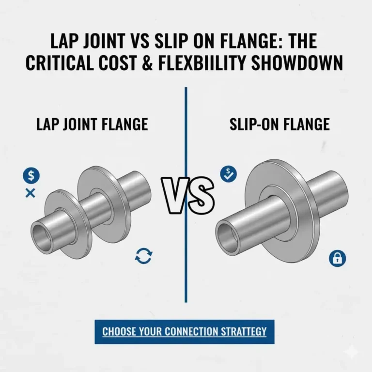
Slip-On Flange vs. Weld Neck Flange vs. Socket Weld Flange
Choosing the right flange involves a trade-off between cost, ease of installation, and system performance. Slip-on flanges are most frequently compared against Weld Neck (WN) and Socket Weld (SW) flanges.
Here is a summary of the key differences:
Comparison of Flange Installation & Performance
| Feature | Slip-On (SO) Flange | Weld Neck (WN) Flange | Socket Weld (SW) Flange |
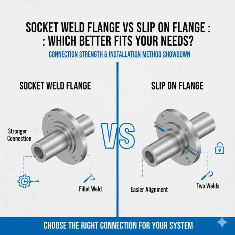
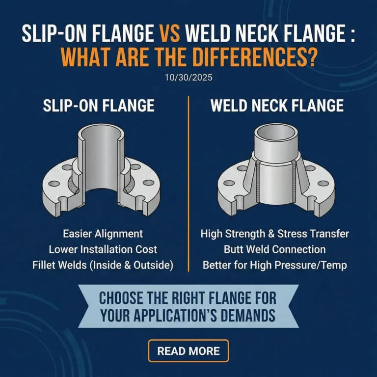
| Welding Method | Two fillet welds (inside & outside) | One butt weld (at the tapered neck) | One fillet weld (outside only) |
| System Strength | Good (Approx. 2/3 of WN strength) | Excellent. Best for high pressure. | Good, but only used for small pipes. |
| Pressure Class | Best for Low-Pressure (e.g., Class 150/300) | Suitable for all pressure classes (up to 2500) | Best for Low-Pressure (Class 150/300) |
| Use Case | Low-pressure, non-critical utilities (e.g., water) | High-pressure, high-temp, critical service | Small-bore pipe only (e.g., 2″ and smaller) |
| Installation | Easy to align; slides onto pipe. | Requires precise alignment & skilled welder. | Easy to align; pipe fits into a socket. |
| Initial Cost | Low Cost | High Cost | Low Cost (but limited in size) |
| Weld Inspection | Internal weld is difficult to inspect. | Butt weld is easy to inspect (via X-ray/RT). | Weld is difficult to inspect. |
FAQ
how to weld a slip on flange
To properly install a slip-on flange, you must perform two separate fillet welds.
Positioning: First, you slide the flange onto the pipe. The flange’s inner diameter is slightly larger than the pipe’s outer diameter to allow this. The critical step is that the end of the pipe must not be flush with the face of the flange. You must pull the pipe back to create a gap. A common industry rule for this gap is “the pipe wall thickness + 1/8 inch”. This gap is essential because it prevents the heat from the internal weld from warping or distorting the flat sealing face of the flange.
Welding: Once positioned, you weld in two places:
The Outside Weld: You perform a fillet weld around the entire outside, connecting the hub (the thickest part) of the flange to the outer diameter of the pipe. This is the primary structural weld that provides the connection’s strength.
The Inside Weld: You then lay a second fillet weld on the inside, joining the bore of the flange to the inner diameter of the pipe. This weld provides secondary strength and an additional seal to prevent leaks.
According to the ASME B31.3 piping code, this double-weld (inside and outside) is mandatory for services that are subject to severe erosion, cyclic loading, or are flammable or toxic.
what is a slip on flange used for
A slip-on flange is primarily used for low-pressure, non-critical piping applications.
Their main advantages are a lower initial cost and easier installation. They are more “forgiving” during assembly because the pipe does not have to be cut to an exact length, and the flange can be easily slid and rotated to align the bolt holes, which speeds up fabrication.
You will commonly find them in systems such as :
Cooling water and fire protection lines
Heating, Ventilation, and Air Conditioning (HVAC) systems
Water treatment plants
Low-pressure compressed air lines
This convenience comes at the cost of strength. A slip-on flange has a much lower fatigue life (estimated at one-third that of a weld neck flange). Therefore, they should never be used in high-pressure, high-temperature, high-vibration, or severely cyclic services.
what gaskets do you use with slip on flanges
To choose the right gasket, you must look at the flange’s face, not its “slip-on” style. The installation method (slip-on) is separate from the sealing surface (the face).
There are two common faces for slip-on flanges:
Raised Face (RF): This is the most common type. It features a “raised” circular surface around the bore. For an RF flange, you must use a Ring Gasket. This is a circular gasket that fits inside the bolt circle and can be made of non-metallic (like compressed non-asbestos fiber) or semi-metallic (like a spiral-wound) material. The RF design concentrates the bolt pressure onto this smaller area, creating a stronger seal.
Flat Face (FF): This flange’s entire sealing surface is perfectly flat. It is used when connecting to brittle equipment, like cast iron pumps or valves. Using an RF flange here could crack the brittle flange. For an FF flange, you must use a Full-Face Gasket. This gasket covers the entire flange face and has holes cut out for the bolts to pass through.
can slip on flanges be used for steam
Yes, but only for low-pressure steam and non-critical utility steam, typically in Class 150 or Class 300 systems.
The biggest problem with steam is not just the pressure; it’s the thermal cycling—the process of the pipe heating up and expanding, then cooling and contracting. This cycle puts enormous fatigue stress on all the welded joints.
Slip-on flanges have a low fatigue life due to their two-fillet-weld design. The ASME B31.3 code specifically warns against using slip-on flanges in services “where many large temperature cycles are expected,” as this can lead to fatigue cracking at the welds.
For any high-pressure steam or any critical steam line, the industry standard and required choice is a Weld Neck Flange. Its full-strength butt-weld design is far more reliable for handling the stresses of steam service.