
When comparing lap joint vs slip on flange options, the real decision is usually “maintenance flexibility vs welded rigidity,” plus how you want to spend money: up-front purchase price or lifecycle cost.
A slip-on flange (SO) becomes a fixed welded joint (typically double fillet weld).
A lap joint flange (LJ) is a two-piece assembly (stub end + loose backing flange) that can rotate for bolt-hole alignment and can be dismantled without cutting a weld.
In most projects, the correct selection is driven by (1) how often the line will be opened, (2) corrosion/alloy strategy, and (3) external piping loads (bending, vibration, thermal movement).
For dimensional/pressure-temperature ratings, the governing references are typically ASME/ANSI B16.5 (standard flanges) and ASME B16.9 (stub ends), plus the project piping code (often ASME B31.3 for process piping). If your sizes exceed the B16.5 scope, confirm the correct large-diameter standard (commonly ASME B16.47) via ASME B16.47 large-diameter flange guidance.
Typical project mix (illustrative engineering range): Slip-on flanges often dominate utility headers and non-cyclic services, while lap joint flanges are concentrated in corrosive services or skids needing frequent dismantling. Typical engineering range, affected by service class, vibration, maintenance plan, and owner specifications.
| Flange Type | Typical Share in a Mixed Industrial Facility (Illustrative Range) |
|---|---|
| Slip-On Flanges | 50–75% (utility / non-cyclic lines where welded rigidity is acceptable) |
| Lap Joint Flanges | 10–35% (corrosive alloy strategy or frequent dismantling points) |
With Sunhy’s 36 years of stainless steel flange manufacturing experience, you can source both configurations with consistent machining control and documentation (material traceability, dimensional inspection, and fit-up consistency). Browse common options here: stainless steel flanges.
Lap Joint vs Slip On Flange: Cost & Flexibility
Cost Comparison
Slip-on flanges often win on unit price; lap joint flanges can win on lifecycle cost when alloy strategy and maintenance downtime are included.
When you compare lap joint vs slip on flange options, separate cost into four buckets:
(1) purchase price,
(2) welding hours and weld procedure complexity,
(3) inspection/NDT expectations, and
(4) downtime when the line must be opened. Slip-on flanges typically cost less to buy, but they are welded to the pipe and become “permanent hardware.” Lap joint assemblies are typically more expensive in parts count (stub end + backing flange), but can reduce expensive-alloy mass and reduce downtime on equipment that must be opened repeatedly.
Here is a quick look at indicative market pricing examples (use as order-of-magnitude only; project pricing varies by schedule, facing, certification, and volume):
| Flange Type | Pipe Size | Price |
|---|---|---|
| Lap Joint | 1/2 in. | $78.64 |
| Lap Joint | 1-1/2 in. | $128.89 |
| Lap Joint | 2-1/2 in. | $147.54 |
| Slip-On | 1-1/2 in. | $15.39 |
| Slip-On | 6 in. | $304.99 |
Installed-cost reality (engineering view): A slip-on flange typically requires two fillet welds and, in many owner specifications, more conservative service placement (avoid high vibration/severe cyclic). A lap joint assembly requires a butt weld of the stub end to the pipe, but the backing flange itself is not welded and can be reused in some maintenance scenarios (subject to condition and spec).
| Flange Type | Material Cost Considerations | Manufacturing / Fabrication Cost Considerations |
|---|---|---|
| Lap Joint Flange | Supports “alloy where it matters”: expensive alloy on the stub end only; backing flange can be a different material where permitted by spec. | Stub end butt weld + fit-up; backing flange alignment is faster. Savings often appear in downtime and in alloy mass reduction. |
| Slip-On Flange | Lower unit price, but flange body is fully tied to the line material class; alloy upgrades can become expensive on large sizes. | Two fillet welds + higher sensitivity to weld profile/fit-up. If the joint must be opened later, removal usually means cutting/grinding and rework. |
Engineering example (cost + alloy strategy): A chloride-bearing utility line that occasionally sees washdown chemicals may be upgraded from 304 to 316L. If the same line is later reclassified to a more aggressive service (e.g., higher chlorides + temperature), plants sometimes push to duplex or 6Mo at dismantling points only. Using a lap joint stub end in the higher-alloy grade while keeping a compatible backing flange strategy (per piping class and corrosion policy) can reduce the “alloy weight” you purchase—especially at larger diameters. If you’re comparing common stainless grades, see: 304 vs 316 stainless steel. Typical practice; final material pairing must follow owner specs and galvanic/corrosion review.
Practical cost checklist before you decide:
- How many planned openings per year? Strainers, heat exchangers, sample stations, filters, and skid tie-ins often justify lap joints.
- Is the line alloy-driven? If the corrosion allowance or alloy grade dominates cost, lap joints can be a cost lever.
- Is downtime expensive? If opening the joint means shutting a unit, “easy dismantle” often pays back quickly.
- What is the external load state? If the flange sees bending (unsupported spool, heavy valve, thermal growth), lap joints can be the wrong tool.
Sunhy can supply both slip-on and lap joint flange configurations with controlled tolerances and documentation, so the selection can focus on joint function rather than availability.
Flexibility Comparison
Lap joint flanges deliver alignment and dismantling flexibility; slip-on flanges deliver welded rigidity and predictable load transfer.
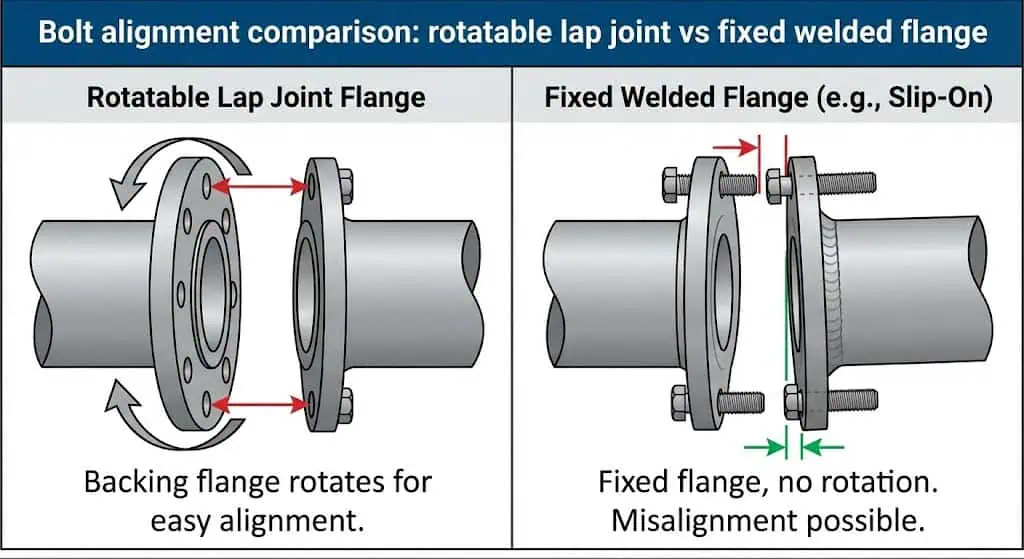
When you evaluate lap joint vs slip on flange flexibility, lap joint flanges stand out because the backing flange is free to rotate around the stub end. That rotation reduces bolt-hole alignment time on field tie-ins and helps when piping tolerances stack up (especially on skids, retrofits, or tight racks). Lap joints also simplify repeated dismantling because the backing flange is not welded to the pipe.
- Fast bolt alignment: Rotatable backing flange lets the fitter “chase” the bolt pattern without forcing the pipe.
- Maintenance access: You can dismantle without cutting a welded flange off the pipe.
- Better for awkward fit-ups: Useful on spool pieces that must be removed for equipment pull/cleaning.
- Alloy strategy support: Stub end material can be aligned to corrosion needs while controlling total alloy mass.
Where lap joints are a poor trade: If the joint sits on an unsupported span, near a vibrating pump discharge, or where external bending is high, the reduced rigidity of a lap joint assembly can accelerate gasket issues or stub-end distortion. In those locations, many piping classes prefer weld neck (or other higher-rigidity designs) instead of either lap joint or slip-on.
Slip-on flanges become fixed after welding. You gain a rigid, compact joint, but you lose adjustability after installation. If the flange has to be opened later, removal is usually destructive (cut/grind), which can push you into extra rework and schedule risk.
Here is a side-by-side comparison:
| Feature | Slip-On Flanges | Lap Joint Flanges |
|---|---|---|
| Alignment Flexibility | Limited flexibility, fixed once welded | High flexibility, rotatable backing flange |
| Ideal for Frequent Removal | Not ideal; removal usually requires cutting/grinding | Suitable when frequent disassembly is planned |
Quick Recommendation
Choose slip-on flanges for cost-sensitive, welded installations with stable loads. Select lap joint flanges for alignment flexibility, repeated dismantling points, or alloy-cost control—provided external loads are low.
If your project needs a simple, budget-friendly solution on stable utility services, slip-on flanges are often acceptable and widely used. If you work with complex piping layouts, retrofit tie-ins, or equipment that must be opened routinely, lap joint flanges can reduce man-hours and downtime. If the service is severe cyclic/vibration/high bending, treat both options cautiously and review the piping class—many systems move to higher-rigidity flange designs for those conditions.
Tip: If a joint will be opened more than a few times over its life (filters, heat exchangers, removable spools), evaluate lap joint flanges early. If a joint will never be opened and sees stable loads, slip-on can be a practical choice.
You can rely on Sunhy to provide high-quality flanges for either approach—then let engineering conditions, not habit, decide the final selection. (If you want a fast refresher on flange basics, see: what is the function of a flange.)
What Is a Slip-On Flange?
Slip-On Flange Definition
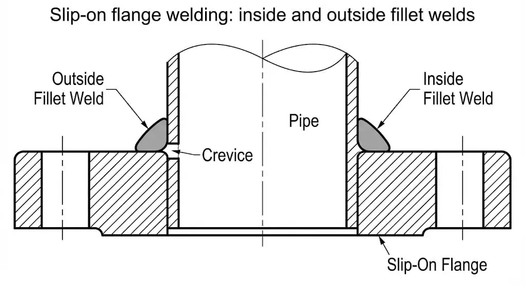
A slip-on flange is a ring that slides over the pipe end and is welded in place for a secure connection.
You install it by slipping the flange over the pipe OD, setting the pipe projection as required for the inside fillet weld, then welding on both the inside and outside. This design is forgiving for fit-up and is common in utility systems. Slip-on flanges are standardized for dimensions and drilling patterns under common flange standards (often ASME/ANSI B16.5 for standard sizes and ratings; larger diameters can be covered by other documents listed under flange standards depending on scope).
Engineer’s fit-up note (leak prevention): slip-ons fail more often from fit-up and welding control than from the gasket itself. Common shop practice is to leave a small stand-off (pipe end slightly back from the flange face) so the inside fillet weld can be placed without creating a large crevice or undercut at the bore transition. Final fit-up should follow the qualified WPS and project fabrication spec.
Key Features of Slip-On Flanges
Slip-on flanges prioritize fast fit-up and economy, with trade-offs in rigidity and fatigue tolerance versus higher-integrity flange types.
You benefit from several practical features when you choose this flange type:
- Simple alignment before welding: flange can be positioned and squared on the pipe easily.
- Fabrication speed: no pipe bevel is needed for a butt weld; fit-up is faster in many shops.
- Lower purchase cost: commonly less expensive than weld neck or specialty assemblies.
- Wide availability: stocked in common sizes/classes for utility service.
- Compact geometry: can be easier to place in tight racks than some longer-hub designs.
Engineering cautions (where slip-on causes trouble): vibration and cyclic bending can concentrate stress at fillet weld toes; and crevice corrosion can initiate at the inside fillet region in aggressive chlorides if surface condition/passivation is poor. These are the reasons many owner specs limit slip-on use in rotating-equipment discharge or severe cyclic services.
Here is a quick comparison table (concept-level):
| Feature | Higher-Rigidity Flange Joints (Example Concept) | Slip-On Flanges |
|---|---|---|
| Attachment Method | Typically full-penetration butt weld | Slip over pipe, then fillet welded (ID & OD) |
| Rigidity Under Bending | Higher | Moderate |
| Alignment Sensitivity | More critical | More forgiving |
| Typical Placement | Critical / cyclic / higher loads | Utility / stable-load services |
Sunhy’s slip-on flange products undergo dimensional checks and documentation control. On site, joint success still depends on welding quality, gasket selection, bolt tightening method, and external pipe supports.
Typical Uses
Slip-on flanges are commonly used in low-to-moderate pressure utility systems where external loads and cyclic conditions are controlled.
These flanges work well in many non-critical services:
| Industry Sector | Application Example | Why Slip-On Flanges Are Effective |
|---|---|---|
| Oil & Gas | Cooling water, non-cyclic utility lines | Economical where vibration/cyclic loading is low |
| Chemical Processing | Non-hazardous utility headers, low-cycling services | Fast fabrication with predictable fit-up |
| Power Generation | Cooling-water loops, auxiliary systems | Speed of installation in large pipe yards |
| Water Treatment | Large-diameter water runs | Common, cost-effective for stable service |
| HVAC | Chilled water piping | Moderate pressure, simple assembly |
| Marine & Offshore | Ballast water, non-critical auxiliary piping | Speed and cost matter, but loads must be reviewed |
| Food & Beverage | Utility water/steam (non-product contact), CIP utility where permitted | For product-contact sanitary lines, clamp/sanitary standards are typically preferred |
| Agriculture | Irrigation pipelines | Economical for large diameter assemblies |
You also use slip-on flanges to connect pipes, valves, and pumps in accessible utility locations where inspection is possible and where later dismantling is unlikely. If frequent disassembly is expected, consider whether a lap joint (or other maintenance-friendly connection) reduces future rework.
What Is a Lap Joint Flange?
Lap Joint Flange Definition
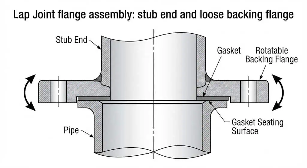
A lap joint flange is a two-piece assembly (stub end + loose backing flange) designed for easy alignment and dismantling in piping systems.
The stub end is butt welded to the pipe. The backing flange slides over the stub end and is not welded, allowing it to rotate freely for bolt-hole alignment. The gasket seats against the stub end face and the mating flange face; the backing flange primarily provides bolt load and alignment rather than being the sealing face itself. Lap joint flanges and stub ends are commonly supplied in line with standard flange/fitting dimensions (often referencing ASME/ANSI B16.5 for flange patterns and ASME B16.9 for stub ends, depending on project spec).
| Characteristic | Description |
|---|---|
| Construction | Two-piece: stub end (welded) + backing flange (loose/rotatable) |
| Key Functional Benefit | Rotational bolt-hole alignment and easy dismantling without cutting a welded flange |
| Material Strategy | Stub end can be selected for corrosion resistance; backing flange can be optimized per spec and environment |
| Best-Fit Applications | Low external loads + frequent access points + corrosive/alloy-driven lines |
Key Features of Lap Joint Flanges
Lap joint flanges are chosen for maintenance access and alignment speed, not for maximum rigidity.
You benefit from several unique features:
- Rotational alignment: the backing flange rotates for fast bolt alignment during fit-up.
- Maintenance-friendly dismantling: the joint can be opened without cutting a welded flange off the pipe.
- Alloy cost control: the corrosion-resistant material can be concentrated at the wetted stub end (where permitted).
- Fast retrofit tie-ins: reduces “field fight” on bolt pattern alignment in constrained racks or skids.
Common engineering limitations: Lap joints are less rigid than welded slip-on joints in bending, and the stub end can distort if external loads are high. On lines with heavy valves, poor supports, or thermal movement, lap joints can leak simply because the gasket load becomes non-uniform under bending. This is a support/design issue as much as it is a flange-type issue.
| Feature | Description |
|---|---|
| Rotational Alignment | Backing flange rotates for easy bolt alignment |
| Quick Dismantling | Open joint without destructive removal of a welded flange |
| Material Flexibility | Stub end can be corrosion-optimized; backing flange strategy follows project spec |
| Rigidity Under Bending | Lower than more rigid flange designs; external loads must be controlled |
Tip: A lap joint is a good “maintenance joint” only if the piping is properly supported and guided. If the joint is carrying bending loads, you will chase gasket leaks no matter how good the gasket is.
Typical Uses
You find lap joint flanges where frequent dismantling, corrosion-driven alloy strategy, or awkward bolt alignment makes them worth the trade-off.
Typical placement is on equipment nozzles, removable spools, strainers/filters, and skid tie-ins—especially in corrosive services where alloy cost is high.
- Petrochemical (maintenance points, corrosion-driven alloy lines)
- Oil and Gas (skid tie-ins, filter/strainer access spools)
- Water Treatment (chemical dosing skids and removable spool pieces)
- Food and Beverage (utility/CIP access points where sanitary joint types are not required)
- Chemical Processing (corrosive services where alloy strategy is a cost driver)
- Offshore and Onshore Engineering (retrofit tie-ins where bolt alignment is difficult)
- Paper Plants (frequent cleaning/maintenance spools)
- Fertilizer Production (corrosive services with planned access)
- Environmental Engineering (chemical handling skids with periodic dismantling)
- Power Projects (auxiliary systems with scheduled maintenance access)
- Mining (abrasive slurries where spool replacement is planned)
- Shipyards (fit-up alignment advantages during installation)
- Mechanical Manufacturing (skid packages and modular assemblies)
- Food and Pharmacy (utility systems; product-contact sanitary standards are typically separate)
Sunhy manufactures lap joint flanges and matching stub ends to standard dimensions with controlled machining. In the field, successful performance still depends on gasket selection, bolt tightening method, and controlling external loads through supports and guides.
Lap Joint vs Slip On Flange: Head-to-Head Comparison
Pressure Handling
Pressure capability is not only a “rating number”—it is a combination of flange rating, stub-end geometry, gasket seating, and external load control.
Both slip-on and lap joint components are produced to standardized flange patterns and pressure-temperature tables under common standards. In practice, many owner specifications place lap joints primarily in lower-load locations because the assembly is less rigid under bending and can lose gasket compression when the line moves or is poorly supported. Slip-ons are also often placed in stable-load services because fillet-weld geometry can be more fatigue-sensitive than butt-weld joints in severe cyclic conditions. (For a quick internal reference on ratings/terms, see: ANSI flanges guide.)
The table below is a typical project specification tendency (not a universal limit). Always confirm against the piping class, code, and project standards:
| Parameter | Slip-On Flanges | Lap Joint Flanges |
|---|---|---|
| Typical Placement Envelope (Owner Spec Trend) | Utility / stable-load services; often limited by vibration/cyclic rules in the piping class | Maintenance points / corrosive alloy strategy / low external loads; often limited in high bending or severe cyclic areas |
| Common “Comfort Zone” (Illustrative) | Class 150–300 (varies by service and spec) | Class 150–300 (varies; external loads often govern more than pressure) |
Field lesson: Many “pressure leaks” at lap joints are actually bending/load leaks. If the spool is mis-supported, the backing flange tilts, the gasket load becomes uneven, and you see weeping—especially during thermal transients.
Installation & Maintenance
Lap joint flanges simplify bolt alignment and planned dismantling. Slip-on flanges simplify initial fit-up, but later removal is usually destructive.
You install lap joint flanges by welding the stub end to the pipe, then sliding and rotating the backing flange for bolt alignment. This can save time on tie-ins. Slip-on flanges require welding both inside and outside; the joint becomes rigid and compact, and initial installation can be fast—especially on repetitive utility work.
Engineer’s maintenance note: If your maintenance plan includes removing a spool (filters, exchangers, flow meters), lap joints reduce future hot work. If the joint will never be opened, slip-on can reduce parts count.
Here is a comparison table for installation and maintenance (typical behavior):
| Flange Type | Installation Time | Initial Cost | Maintenance/Dismantle Effort | Sealing Performance | Durability Under External Loads |
|---|---|---|---|---|---|
| Slip-On Flange | Fast fit-up; welding required (ID & OD) | Lower unit cost | Higher if dismantling is needed later (cut/grind/rework) | Good when gasket + bolt-up are controlled; sensitive to weld fit-up quality | Moderate; fillet-weld stress concentration can be a limiter in severe cyclic/vibration |
| Lap Joint Flange | Stub end butt weld + fast bolt alignment | Higher parts cost | Lower for planned dismantling (no welded flange removal) | Good when gasket seating and external loads are controlled; stub-end face condition matters | Lower rigidity; not preferred where bending loads are significant |
You benefit from Sunhy’s manufacturing consistency and certification control, but field reliability still depends on bolt tightening method (controlled sequence), gasket compatibility, and pipe support condition. If your scope includes other flange types for critical services, compare options in: flange standards.
Adaptability
Lap joint flanges provide superior adaptability for custom projects and retrofit tie-ins, provided the joint is not used as a “structural hinge.”
You gain flexibility with lap joint flanges because they rotate and adjust easily. This helps align bolt holes and fit complex piping layouts without forcing the line into position (which can preload the joint). Lap joint assemblies also allow an alloy-cost strategy at the wetted stub end in some corrosive services. Slip-on flanges are less adaptable after installation because the flange is welded in place.
Consider these factors when choosing flanges for custom projects:
- External loads: evaluate bending moments from unsupported spans, valve weight, and thermal growth.
- Maintenance philosophy: define which joints will be opened on a schedule and design for that reality.
- Corrosion strategy: confirm whether stub end/backing flange material pairing is permitted and how galvanic/corrosion is managed.
- Inspection plan: clarify what NDT is required at welds and whether access is available.
- Procurement consistency: ensure stub end pattern (short/long), facing, and thickness match the flange pattern and gasket.
- Gasket and facing: confirm seating width and surface finish requirements for the selected gasket type.
- Installation control: specify bolt-up method (torque/turn-of-nut/tensioning) and tightening sequence.
You can rely on Sunhy’s certified manufacturing and custom solutions to meet your project’s requirements, then lock performance with correct support design and joint assembly discipline. Need a quick B16.5 overview first? Read: What does ASME B16.5 mean?
Practical Applications for Lap Joint Flanges and Slip-On Flanges
When to Choose Lap Joint Flanges
Choose lap joint flanges for planned dismantling points, bolt-alignment constraints, or alloy-cost control—only when external loads are controlled by proper supports and guides.
You benefit most from lap joint flanges where you must regularly inspect, clean, or remove equipment (filters/strainers, exchangers, meters) or where fit-up is constrained. The rotatable backing flange reduces field labor, and the stub end can be selected to match corrosion needs.
| Industry Application | Advantages |
|---|---|
| Oil and Gas | Skid tie-ins and maintenance spools; rotation simplifies fit-up and future dismantling. |
| Petrochemical Refineries | Corrosive services + planned maintenance points; reduces downtime when opening joints. |
| Water Treatment Plants | Chemical dosing skids and removable spools; maintenance access is frequent. |
| Food and Beverage | Utility/CIP access spools (non-sanitary joint types); fast open/close at planned points. |
| Power Generation Plants | Auxiliary systems with scheduled maintenance access; avoid high-bending locations. |
Tip: If a lap joint keeps leaking, check pipe supports first. Many “bad gasket” complaints are actually flange tilt from bending loads or thermal growth.
When to Choose Slip-On Flanges
Select slip-on flanges for cost-sensitive, welded installations in stable-load services where repeated dismantling is not expected.
You achieve fast fit-up and a compact welded joint with slip-on flanges. These flanges work best in utility lines, HVAC systems, fire protection setups, and general water services—especially where supports are adequate and vibration is low.
| Industry/Application | Advantages of Slip-On Flanges |
|---|---|
| HVAC Systems | Quick installation on stable piping; common for chilled water loops. |
| Fire Protection Systems | Cost-effective and standardized for stable service (verify local code/spec). |
| Light Industrial Manufacturing | Compressed air and utility water lines where cyclic loading is limited. |
| Water Treatment Plants | Common for large-diameter water runs with predictable loads. |
Note: Slip-on flanges are a practical choice when you need a welded, fixed joint and you do not expect to dismantle the connection later.
Real-World Examples
Real installations show that flange selection succeeds (or fails) based on load control, maintenance planning, and assembly discipline.
Below are four common field scenarios, written as “problem → cause → fix/prevention.”
| Scenario | What Happened | Root Cause | Fix / Prevention |
|---|---|---|---|
| Filter skid opened monthly (LJ recommended) | Technicians spent hours fighting bolt alignment and replacing damaged gaskets. | Welded flange joints forced the pipe; repeated dismantling damaged gasket faces and hardware. | Use lap joint at planned dismantling points; specify controlled bolt-up and protect sealing faces during maintenance. |
| Corrosive chloride service with large diameter (LJ alloy strategy) | Alloy upgrade cost escalated quickly when every flange had to be high-alloy. | Material strategy placed expensive alloy in non-wetted mass unnecessarily. | Evaluate alloy concentration at stub ends (per piping class); confirm galvanic/corrosion policy and environment controls. |
| Slip-on near vibrating equipment (SO caution) | Intermittent weeping at gasket and toe-cracking indications at fillet weld after operation. | Cyclic vibration + stress concentration at fillet weld toe; supports not tuned for vibration. | Relocate to stable section or upgrade joint design per piping class; improve supports, add vibration control, and follow WPS/profile requirements. |
| Lap joint installed on an unsupported span (LJ caution) | Repeated gasket leaks during heat-up/cool-down cycles. | External bending tilted the backing flange; gasket load became uneven. | Add supports/guides and correct spool alignment; lap joint works when it is not carrying bending moments. |
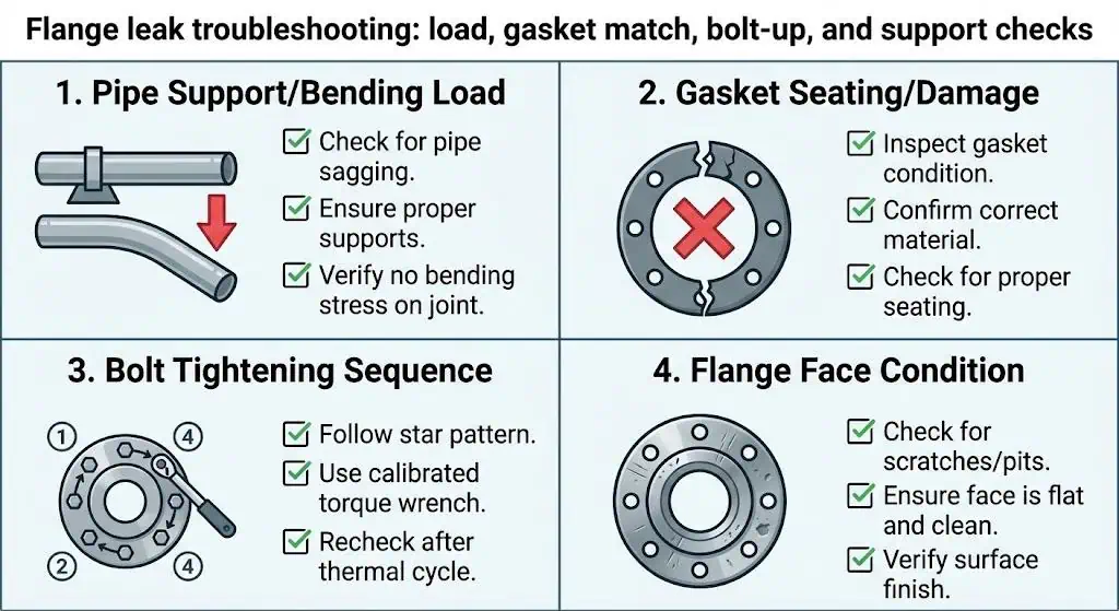
- Practical takeaway: If the joint leaks, don’t jump straight to “bad gasket.” Check flange parallelism, pipe supports, thermal movement, bolt load uniformity, and surface condition on the stub end face (lap joint) or flange face (slip-on).
Field rule: The flange type helps, but joint integrity is built by supports + alignment + gasket match + controlled bolt-up.
Lap Joint vs Slip On Flange: Summary Table
You need a clear comparison to make the right choice for your piping system. The table below highlights the main differences between lap joint flanges and slip-on flanges, focusing on engineering behavior rather than marketing labels.
| Feature | Lap Joint Flange | Slip-On Flanges |
|---|---|---|
| Cost | Higher parts count; can reduce alloy mass and downtime at maintenance points | Lower unit cost; installed cost depends on welding/rework risk |
| Flexibility | Maximum bolt-alignment flexibility; rotatable backing flange | Fixed after welding; limited adjustment |
| Installation | Stub end butt weld + fast alignment | Fast fit-up; double fillet weld required |
| Maintenance | Best for frequent disassembly and inspection | Best for joints not expected to be opened |
| Rigidity Under Bending | Lower; avoid high external loads unless design/supports control them | Moderate; still review cyclic/vibration limits in the piping class |
| Common Failure Drivers | Flange tilt from bending, stub end face damage, poor bolt-up control | Fit-up/weld profile issues, cyclic vibration near equipment, crevice/corrosion at inside fillet region |
Cost
Choose slip-on flanges for the lowest unit cost; choose lap joints when lifecycle cost is driven by alloy strategy and dismantling downtime.
Slip-ons typically cost less to buy. Lap joints typically cost more in parts, but they can pay back quickly at planned maintenance points or on alloy-driven lines where you want to reduce expensive material mass.
Flexibility
Lap joint flanges give you the most alignment flexibility.
You can rotate lap joint flanges for easy bolt alignment. This helps in complex racks, retrofits, and skid tie-ins. Slip-on flanges do not allow movement after welding.
Installation
Slip-on flanges often install faster at first fit-up; lap joints speed up bolt alignment and future dismantling.
You slide slip-on flanges over the pipe and weld them in place. Lap joint flanges need a stub end butt weld first, but then assembly/alignment is typically faster.
Maintenance
Lap joint flanges make planned maintenance simpler; slip-on flanges are better when you do not expect to dismantle the joint.
You can remove and reassemble lap joint flanges without destructive flange removal. Slip-on flanges are typically used where the joint will remain welded for life.
Tip: If a line is likely to be dismantled, design for dismantling. If a line is “install-and-forget,” choose the simplest welded joint that meets the piping class and load conditions.
Choose slip-on flanges for cost savings on stable-load, non-dismantled joints. Select lap joint flanges for alignment flexibility and planned dismantling points.
- Slip-on flanges work best for welded, budget-friendly installations where future dismantling is unlikely.
- Lap joint flanges suit systems that need frequent maintenance access or bolt alignment flexibility—if external loads are controlled.
Best practice: match flange type to service criticality, external loads, and maintenance plan. Then lock performance with correct gasket selection and controlled bolt-up.
FAQ
What is the main difference between a slip-on flange and a lap joint flange?
Slip-on flanges weld directly to the pipe; lap joint flanges use a welded stub end plus a loose backing flange.
Slip-ons become a fixed welded joint (usually double fillet weld). Lap joints weld the stub end to the pipe, but the backing flange is not welded and can rotate for bolt-hole alignment. Lap joints are typically chosen for planned dismantling points and alignment flexibility, while slip-ons are chosen for simple welded joints in stable-load services.
When should you choose a lap joint flange?
Select lap joint flanges where the joint will be opened, bolt alignment is difficult, or alloy strategy drives cost—provided external loads are low.
Lap joints are common at strainers/filters, removable spool pieces, and skid tie-ins. They can reduce downtime and fit-up labor. Avoid lap joints where bending loads, vibration, or severe cyclic movement will tilt the flange and unload the gasket.
Are slip-on flanges suitable for high-pressure applications?
Slip-on flanges can be produced in rated classes, but many piping classes restrict where they are used based on vibration/cyclic risk and joint criticality.
In practice, slip-ons are most common in utility and stable-load services. For high-pressure process-critical or severe cyclic services, many projects shift to higher-integrity flange joints and stricter inspection regimes. Always follow the piping class specification, code requirements, and owner standards.
How do you select the right pipe flange for your project?
Match flange type to pressure/temperature, external loads, maintenance frequency, corrosion/alloy strategy, and inspection plan.
Start with the project piping class (service category) and confirm flange standard, facing, gasket type, bolt material, and assembly method. Then review supports/thermal growth so the joint is not carrying unintended bending. Finally, define whether the joint is a planned dismantling point—if yes, lap joint can reduce lifecycle downtime.
Can you use different materials for lap joint flange components?
Yes, but only if the project specification allows it and corrosion/galvanic behavior is reviewed.
Some systems concentrate corrosion-resistant alloy on the wetted stub end while optimizing the backing flange material. This can reduce alloy mass cost, especially at larger sizes. The final decision must follow the piping material specification, environmental exposure review (external corrosion), and any galvanic isolation requirements.
Helpful external references (official sources):
ASME B16.5 official standard page
ASME B16.47 official standard page
ASME B31.3 official code page
ASTM A182/A182M official specification page
ASTM A403/A403M official specification page


