")
Accurate bolt length calculation is essential for reliable connections in industrial piping systems.
You are not only “making it fit.” Bolt length controls (1) full nut thread engagement, (2) how much elastic stretch the stud can provide to keep gasket stress stable, and (3) whether the joint can be disassembled without cutting fasteners. For standard ASME flange sizes, the fastest path is to cross-check your result against the stud length guidance tied to ASME B16.5 (and ASME B16.47 for large diameters). For joint assembly practices and common failure mechanisms (embedment, relaxation, alignment), use ASME PCC-1.
- Start with the correct flange standard/series (B16.5 vs B16.47), facing type (RF/FF/RTJ), and gasket type/thickness.
- Calculate by stack-up (geometry) and then sanity-check against published flange/bolt charts derived from the ASME dimensions.
- Confirm thread engagement rules for your code and project spec (many piping specs reference ASME B31.3 thread engagement expectations).
ASME Flanges Bolt Length Formula
Stud Bolt Theoretical Length Explained
You calculate stud bolt theoretical length for ASME flanges using a standard stack-up method commonly referenced for B16.5-style flange joints. The goal is simple: the stud must pass through both flanges and gasket, fully engage both nuts, and leave a controlled amount of thread projection for inspection and future removal.
Tip: Before you calculate anything, confirm flange facing type (RF/FF/RTJ) and gasket style. RTJ and insulated joints change the stack-up more than most people expect.
Here is a commonly used method for calculating stud bolt lengths for flanged connections (practical stack-up approach):
| Component | Description | Formula / How to use it |
|---|---|---|
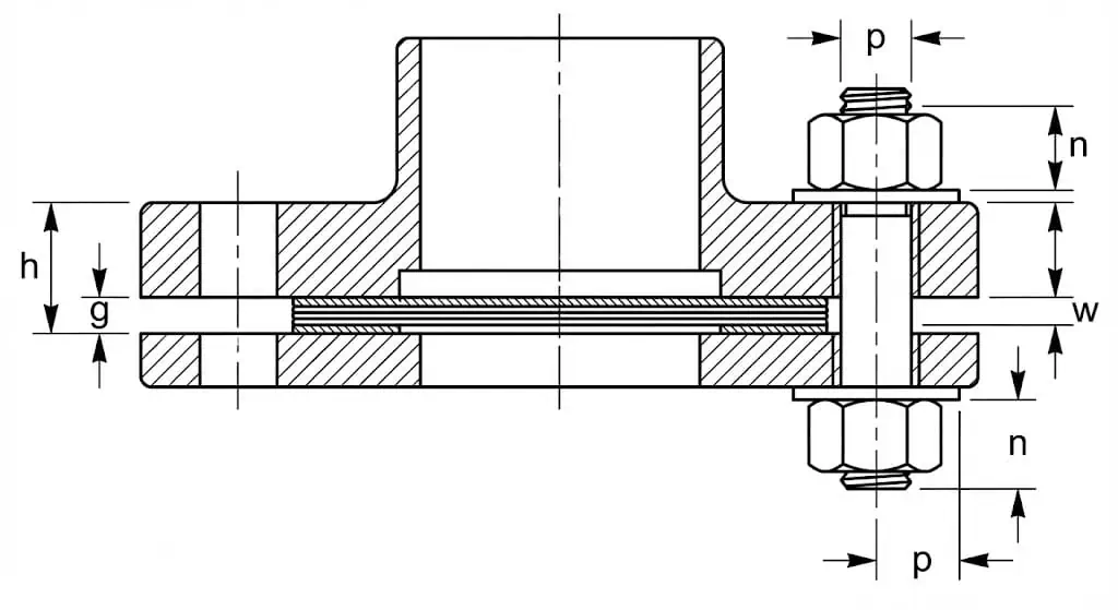
| L | Theoretical length of stud bolt | L = 2 (s + n + h + rf) + g + 2w + p |
| s | Free threads allowance (typical starting point) | s ≈ 1/3 × bolt diameter (verify with project spec) |
| n | Nut height (depends on nut type/standard) | Use the nut height from ASME B18.2.2 (heavy hex vs hex matters) |
| h | Flange thickness to the gasket contact surface | Measure actual flange thickness with calipers (do not rely on memory) |
| rf | Raised face height (or facing feature that adds to thickness) | RF adds height; FF usually rf = 0; RTJ/T&G follow the facing geometry and standard tables |
| g | Gasket thickness | Use the gasket’s actual thickness (spiral wound vs sheet differs) |
| w | Washer thickness (if used) | Add washer thickness on each nut side (2w total) when washers are specified |
| p | Thread projection/protrusion allowance | Plan for controlled projection (often 1–2 exposed threads) and full engagement |
Read the formula as a disciplined stack-up, not as a “magic ASME number.” If you measure the true assembly height (two flange thicknesses + gasket + washers if any) and then add nut heights plus controlled thread projection, you will land on a stud length that assembles cleanly and maintains preload.
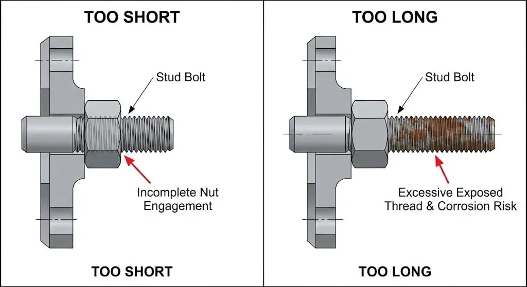
Field failure example (under-length stud): On a Class 600 water injection skid, the studs were short by ~6–8 mm because washer thickness was ignored. The nuts “felt tight,” but one nut side was riding near thread runout. After hydrotest, the joint wept at the low point. Root cause was incomplete nut engagement + uneven gasket compression. Fix: correct stud length, replace galled nuts, reassemble per ASME PCC-1 practices.
Note: If you are using published bolt charts (derived from B16.5/B16.47), verify how “length” is defined (e.g., first thread-to-first thread for studs, and whether points/chamfers are excluded). Vendor charts often include these definitions explicitly.
Required Measurements and Tools
You must measure each component accurately to calculate the correct bolt length. In practice, “nominal” values are fine for a first pass, but you should confirm at least one flange thickness and the gasket thickness from the actual batch (especially for soft gaskets, insulated kits, or spiral wound gaskets that vary by style and winding density).
Here are the key variables and typical units you should record:
| Variable | Unit |
|---|---|
| Flange thickness (each side) | mm or in |
| Facing feature height (RF / recess / groove reference) | mm or in |
| Gasket thickness (uncompressed) | mm or in |
| Nut height (actual nut standard/type) | mm or in |
| Washer thickness (if specified) | mm or in |
| Thread projection target (exposed threads) | threads / mm / in |
You will need these tools:
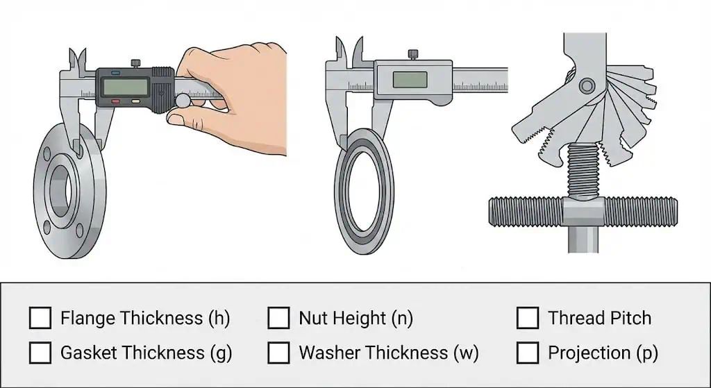
- Caliper or micrometer for flange, washer, and gasket thickness
- Steel ruler or tape measure for overall stud length checks
- Thread gauge (and pitch gauge) for bolt diameter/pitch confirmation
- Depth gauge (helpful for RTJ groove features and counterbores, when relevant)
Dimensional tolerances matter because your calculation has no “safety buffer” if the joint is already tight on length. ASME flange standards include tolerances and dimensional definitions; use the current edition of the applicable standard as the primary reference (B16.5/B16.47). For quick shop-floor context, many fabricators use tolerance summaries consistent with those standards.
The table below is a commonly used tolerance summary for flange dimensional inspection items (verify against your project’s governing standard and inspection plan):
| Dimension | Tolerance |
|---|---|
| Outside Diameter (O.D. ≤ 24″) | +0.125″, -0.0625″ |
| Outside Diameter (O.D. > 24″) | +0.125″, -0.125″ |
| Inside Diameter (I.D. ≤ 10″) | +0.03125″, -0″ |
| Inside Diameter (I.D. > 10″) | +0.0625″, -0″ |
| Contact Face Diameter | +0.0156″, -0.0156″ |
| Bolt Hole Diameter | +0.03125″, -0.03125″ |
| Bolt Circle Diameter | +0.0625″, -0.0625″ |
| Bolt Hole Spacing | +0.03125″, -0.03125″ |
| Thickness (Nominal size ≤ 18″) | +0.125″, -0″ |
| Thickness (Nominal size > 18″) | +0.1875″, -0″ |
Practical takeaway: If flange thickness and gasket thickness drift upward, “borderline” studs become too short. That is why many site specs require a positive thread projection check after final tightening (visual verification is fast and catches the worst cases early).
Bolt Length Factors
Flange and Gasket Thickness
Flange and gasket thickness directly determine the grip (clamped) length of your joint.
Grip length is the total thickness of the materials being clamped between the nut bearing faces (typically: two flange thicknesses + gasket + any washers or insulating kit components). Longer effective grip generally increases bolt elasticity, helping the joint maintain load when the gasket creeps or the flange rotates under pressure/thermal change.
- Thicker flanges and thicker gaskets increase required bolt length.
- Short studs are more sensitive to embedment/relaxation losses; the same loss of joint thickness causes a larger loss in bolt load when the bolt’s effective length is short.
- Do not assume gasket thickness: spiral wound, kammprofile, and sheet gaskets can vary in both thickness and compressibility.
- If you are using RTJ flanges, do not treat them like RF: the facing geometry and ring selection drive different assembly details and can influence length selection practice.
- As a rule of thumb in flange-joint practice, “very short” bolts (low effective length-to-diameter) tend to lose clamp load faster under the same joint settling; confirm your limits and procedure against ASME PCC-1.
Field failure example (gasket swap): A maintenance team replaced a 1.5 mm compressed fiber sheet gasket with a 3.2 mm spiral wound gasket “same size, same bolt pattern.” The old studs barely had visible projection after tightening; the new gasket left several nuts short of full engagement. The joint was reworked with correct stud length and hardened washers to stabilize friction during torquing.
Nut Height and Washer Allowance
Nut height and washer allowance are essential parts of the total assembly height in bolt length calculations.
Do not assume nut height equals nominal diameter. Hex vs heavy hex nuts have different heights, and projects may specify particular standards. Use the nut type and dimensions from recognized fastener standards (e.g., ASME B18.2.2 for inch-series nuts; confirm the metric equivalent if you are working in ISO/DIN hardware).
- Nut height drives how many threads are available for engagement.
- Washers (when specified) protect flange bearing surfaces and can improve torque consistency by reducing surface galling and friction scatter.
- Always add washer thickness to your calculation when washers are required by your bolting procedure or client specification.
Tip: If you see large torque scatter or “sticky” nut rotation in stainless hardware, check for washer requirements and lubrication compatibility before blaming stud length.
Additional Allowances
Additional allowances account for thread projection targets, special kits, and service conditions that affect bolt length selection.
At minimum, you need full thread engagement through the nut. Many piping specs reference the expectation that bolts extend through the nut (or are short by no more than about one thread) and that the joint shows a controlled projection after tightening. For a practical reference used widely in industry discussions of ASME B31.3 thread engagement expectations, see the summary at Portland Bolt (thread engagement).
- Plan for controlled projection. One to two exposed threads is commonly used as a visual indicator of full engagement in many maintenance specs and owner standards.
- If you use flange insulation kits (sleeves, washers, insulating gaskets), add every component thickness into the stack-up—these kits routinely add more than the “small” margins people assume.
- At elevated temperatures, gasket creep and joint relaxation can reduce bolt load over time; longer effective bolt length generally gives better load retention for the same amount of joint settling. Relaxation in bolted flange joints is a known driver of leakage risk, especially across thermal transients (ASME paper on bolted flange relaxation).
- Always confirm flange size, pressure class, facing, bolt diameter/pitch, and nut type before finalizing stud length.
Field failure example (over-length stud): On an outdoor seawater line, over-length studs left excessive exposed thread. Salt spray + stagnant water at the nut face caused crevice corrosion and seized nuts. The next outage required cutting hardware. Fix: select correct stud length, specify protective caps or coatings where allowed, and avoid unnecessary exposed thread length.
By understanding each factor—flange thickness, gasket thickness, nut height, washer allowance, and controlled projection—you can select a bolt length that assembles cleanly and stays maintainable.
Calculation Example for ASME Flanges
Sample Values and Step-by-Step Calculation
You can calculate the correct bolt length for your flange assembly by following a clear process.
The example below is a geometry-based stack-up. In the real world, the “right” projection target depends on your bolting spec and code expectations, so treat protrusion as a controlled requirement, not a guess.
Given:
- Flange thickness: 24 mm (each flange)
- Gasket thickness: 3 mm
- Nut height: 20 mm (per nut)
- Washer thickness: 2 mm (per washer, 2 washers)
- Required protrusion: 6 mm (example target; confirm by thread pitch and spec)
Step-by-step calculation:
- Add up the clamped thickness (grip):
- Two flanges: 24 mm × 2 = 48 mm
- Gasket: 3 mm
- Two washers: 2 mm × 2 = 4 mm
- Grip subtotal = 55 mm
- Add nuts + projection allowance:
- Two nuts: 20 mm × 2 = 40 mm
- Protrusion allowance: 6 mm
- Nuts + projection subtotal = 46 mm
- Total bolt length:
- 55 mm (grip)
- + 46 mm (nuts + projection)
- Total = 101 mm
You should round up to the next commercially available bolt length.
If 105 mm is available, select that size for your assembly, then verify final projection after tightening.
Tip: Convert “protrusion mm” into “threads” using pitch. A 6 mm projection is not the same for M16×2.0 vs M20×2.5.
Using ASME B16.5 Tables and Rules of Thumb
You can use ASME flange dimensional standards as the governing reference for standard flange sizes.
For NPS 1/2 through 24, the applicable baseline standard is ASME B16.5. For NPS 26 through 60, use ASME B16.47. Published flange/bolt charts can speed selection, but you still need to confirm facing and gasket choices (RF vs RTJ charts do not always match).
About “rules of thumb” (like 5:1):
Rules such as “stud length ≈ 5 × diameter” can be useful as a sanity check to avoid extremely short bolts, but they are not a substitute for stack-up and standard tables. Use them to catch obvious errors (e.g., a stud too short to deliver elastic stretch), then return to your measured stack-up and the governing standard.
Summary Table (illustrative only — lengths vary by class, facing, and series):
| Flange Size | Bolt Diameter | “5×D” sanity check length | Standard chart check |
|---|---|---|---|
| 2″ | 16 mm | ≈ 80 mm | Verify against B16.5 chart for your class/facing |
| 3″ | 20 mm | ≈ 100 mm | Verify against B16.5 chart for your class/facing |
| 4″ | 22 mm | ≈ 110 mm | Verify against B16.5 chart for your class/facing |
You should always compare your calculated value with a standard chart and select the value that satisfies full engagement and controlled projection.
If your stack-up result is longer than the chart value, check what changed (gasket thickness, washers, insulation kit, nut type). Do not “force” the chart length onto a non-standard stack-up.
Measuring and Avoiding Mistakes

Measuring Stud Bolts and Hex Bolts
You must measure bolts accurately to ensure a safe and reliable flange connection.
Measure stud length the way your standard or vendor defines it. Many stud charts define length from first thread to first thread (excluding chamfer/point effects). If you are using vendor charts, confirm how points are treated; some references note stud points are typically about 1–2 full threads in length (example chart notes).
| Tool | Description |
|---|---|
| Calipers | Measure flange thickness, washer thickness, gasket thickness, nut height, and bolt diameter. |
| Tape measures | Useful for overall stud length checks and large flange OD checks. |
| Flange measuring tools | Support repeatable measurements of ID/OD/bolt hole dimensions on assemblies. |
Follow these steps to measure stud bolts and hex bolts:
- Confirm the fastener type and dimensional standard (bolt head/nut geometry is defined by standards such as ASME B18.2.1 and ASME B18.2.2).
- Measure diameter and thread pitch (wrong pitch is a silent failure on-site).
- Measure total stud length using the defined method (first thread-to-first thread where applicable).
- Verify nut height and washer thickness if used.
- After assembly, visually verify engagement/projection on both sides.
| Dimension Type | Description |
|---|---|
| Head Height | For hex bolts, confirm head geometry matches the governing fastener standard. |
| Width Across Flats | Ensures correct wrench fit and avoids rounding during tightening. |
| Body Diameter | Confirms fit through bolt holes and compatibility with nuts. |
| Bolt/Stud Length | Measure using the defined length method for the fastener type. |
| Thread Length / Pitch | Controls engagement and prevents mismatched nut/stud combinations. |
| Final Engagement Check | After tightening, confirm full nut engagement and controlled projection. |
Stainless galling example (assembly problem that looks like “wrong length”): On stainless bolting, nuts can seize during torquing due to galling. The installer stops early, leaving low preload and leaks—then blames stud length. If your application allows, use correct lubrication and compatible nut/bolt pairing; stainless fastener galling mitigation is discussed in technical references such as the NASA Fastener Design Manual (e.g., plated nuts used as lubricating/corrosion barrier concepts). In piping work, always confirm what lubricants are permitted and chemically compatible with process conditions.
Common Errors in Bolt Length Selection
You can avoid mistakes by using a repeatable checklist tied to your governing standards and your joint procedure.
Many errors happen when installers assume “standard gasket,” ignore washers/insulation kits, or do not check thread engagement after tightening. If your piping code/spec references B31.3 engagement expectations, the practical interpretation (extend through nut or short by no more than about one thread) is summarized in the thread engagement guidance at Portland Bolt.
Common mistakes include:
- Using the wrong bolt length for the real flange thickness (measured vs nominal).
- Ignoring washer thickness or insulation kit stack-up.
- Assuming nut height without confirming the nut standard/type.
- Overlooking controlled projection and post-tightening engagement checks.
- Not verifying thread pitch and nut compatibility (especially in mixed metric/inch environments).
You can reduce mistakes by ensuring proper training for all personnel.
Training levels range from on-boarding to specialist and inspector training for critical joints. Many organizations base bolting training frameworks on PCC-1 practices and terminology.
| Training Level | Description |
|---|---|
| On-Boarding Training | Minimum for staff working on bolted flange joint applications. |
| Bolting Trainee | Recommended for assembly personnel working under supervision. |
| Bolting Specialist | For personnel managing critical joints and procedures in demanding environments. |
| Inspector Training | For those verifying engagement, tightening records, and joint acceptance. |
Tip: After final tightening, do a quick “nut end” inspection around the flange: verify uniform flange gap (if applicable) and confirm engagement/projection is consistent on all studs.
You ensure accuracy and compliance by following these key steps for bolt length calculation:
| Step | Description |
|---|---|
| 1 | Measure flange, gasket, nut, and washer/kit thickness from the actual items. |
| 2 | Add allowances for controlled projection (threads) and any special hardware. |
| 3 | Cross-check against the applicable flange standard (B16.5 or B16.47) and reliable charts. |
| 4 | After tightening, confirm full thread engagement and acceptable projection based on your code/spec (see thread engagement guidance). |
You improve safety and performance by using a checklist and aligning your assembly practice to recognized guidance.
- Proper bolt length supports effective sealing and reduces the chance of uneven gasket compression.
- Correct installation helps prevent leaks and flange rotation/warping.
Accurate bolt preload keeps your flange assembly reliable over time. Treat bolt length as part of the preload control system: if the fastener cannot fully engage and stretch as intended, no torque procedure will rescue the joint.
FAQ
How do you choose the correct bolt length for asme flanges?
You add up the real stack-up height and then verify engagement after tightening. A practical sequence is:
- Measure: two flange thicknesses + gasket + washers/insulation components.
- Add: two nut heights (confirm nut type) + a controlled projection target.
- Cross-check: compare with a reliable chart derived from the correct ASME flange standard (B16.5 vs B16.47).
What tools help you measure flange and bolt dimensions?
You use calipers, tape measures, and thread gauges for accurate measurements. For repeatability on-site:
- Calipers/micrometers: flange, washer, and gasket thickness; stud diameter.
- Tape measure/ruler: overall stud length verification.
- Thread/pitch gauge: confirm thread size and pitch before assembly.
Why is bolt protrusion important in flange assembly?
You need controlled protrusion to confirm full engagement and maintainability. Too little projection can signal incomplete engagement; too much increases corrosion exposure and can interfere with access. Many piping specs expect full engagement through the nut (often “extend through the nut” or within about one thread), which is commonly summarized in industry guidance such as thread engagement references.
- Supports visual inspection of engagement after tightening.
- Reduces the chance of running a nut onto thread runout near the stud end.
- Improves future disassembly compared with “flush/no thread” conditions.
Can you use washers with every flange connection?
You can use washers if required by your application, client spec, or bolting procedure. In many cases, washers help protect flange bearing surfaces and stabilize friction during tightening—but they must be included in the bolt length stack-up.
- Washers protect flange surfaces and distribute load.
- Washers add thickness and increase required stud length.
- Use hardened washers where specified for consistent tightening behavior.
What happens if you use the wrong bolt length?
You risk leaks, joint instability, and unsafe connections. Typical outcomes are:
- Too short: incomplete nut engagement, reduced preload margin, higher leak risk under pressure/thermal cycles.
- Too long: access problems, unnecessary exposed threads (corrosion/seizure), and installation delays.
- Corrective action: replace fasteners and reassemble using a measured stack-up plus a standard/chart cross-check.


