Stainless Steel Pressure Vessel Flanges
Pressure vessel flanges are among the most critical connection points in high-stress systems such as reactors, boilers, and heat exchangers. These components have a dual design objective: to provide a maintainable access point when needed, and to ensure an absolute zero-leakage seal under conditions of extreme pressure, high temperatures, and cyclical loading.
Types of Pressure Vessel Flanges We Supply
 Stainless Steel Flanges
By Design Type
By Standard & Class
Advanced Materials
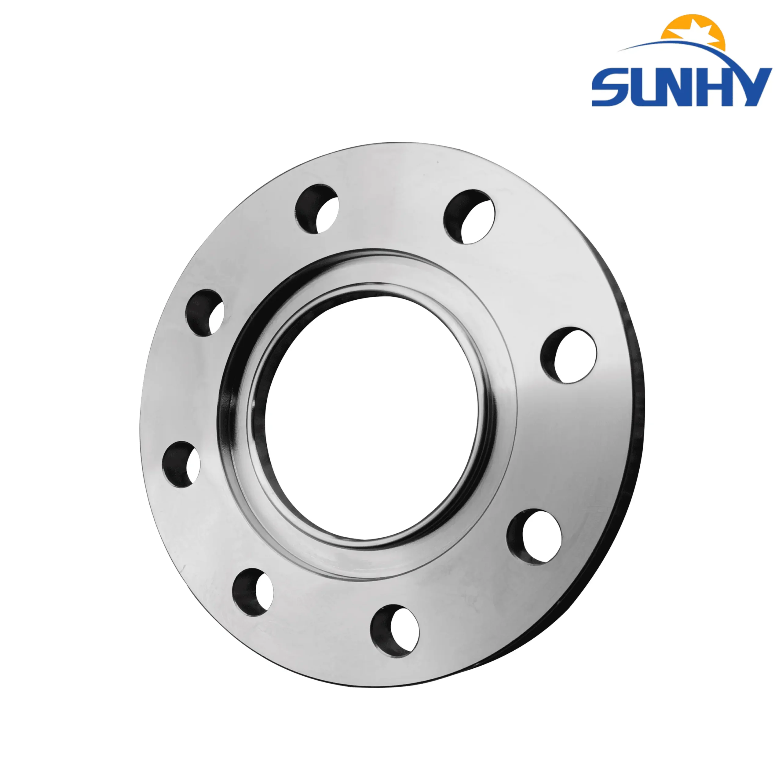
8-Bolt Stainless Steel Flexible Joint Flange
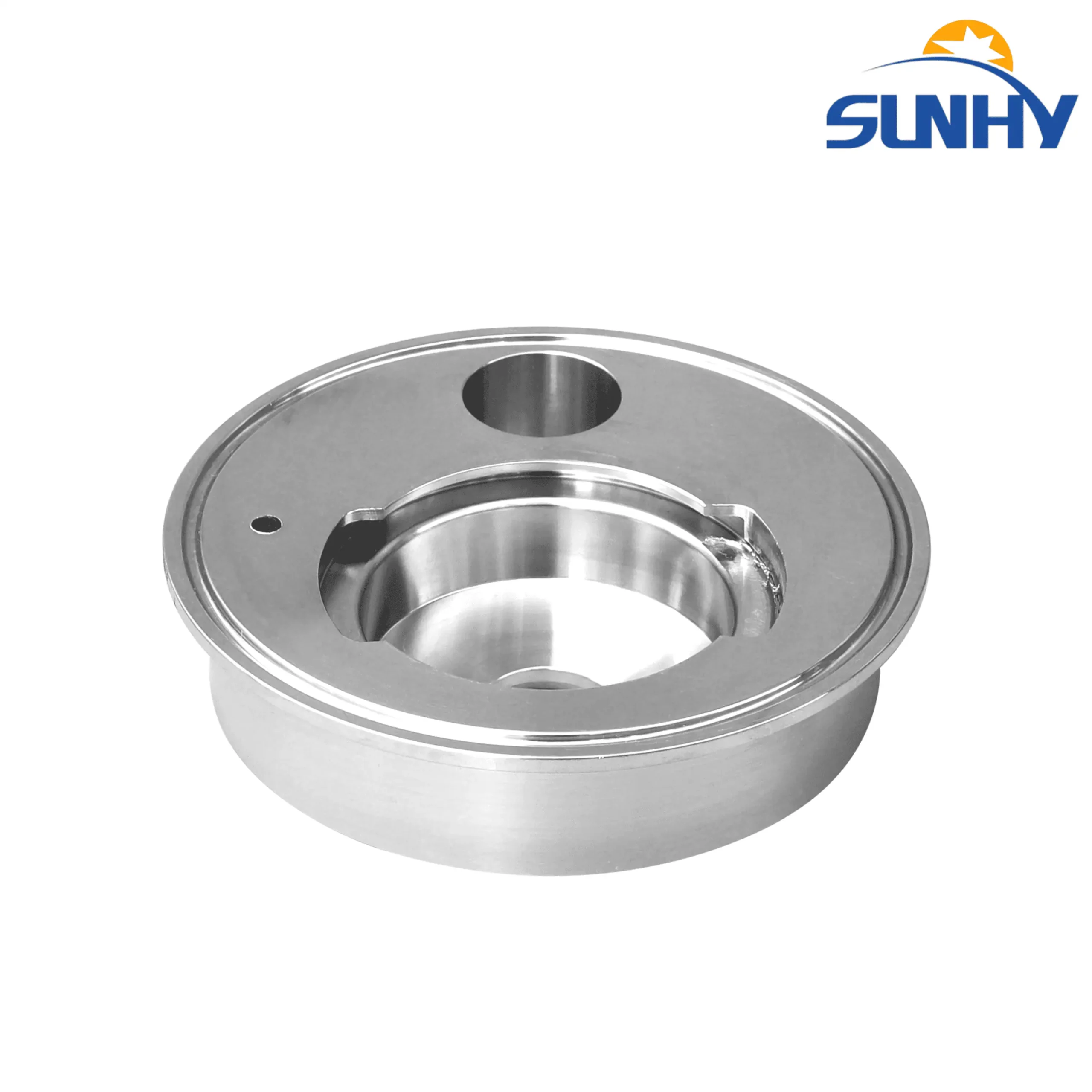
Stainless Steel Machined Core Seat Bottom
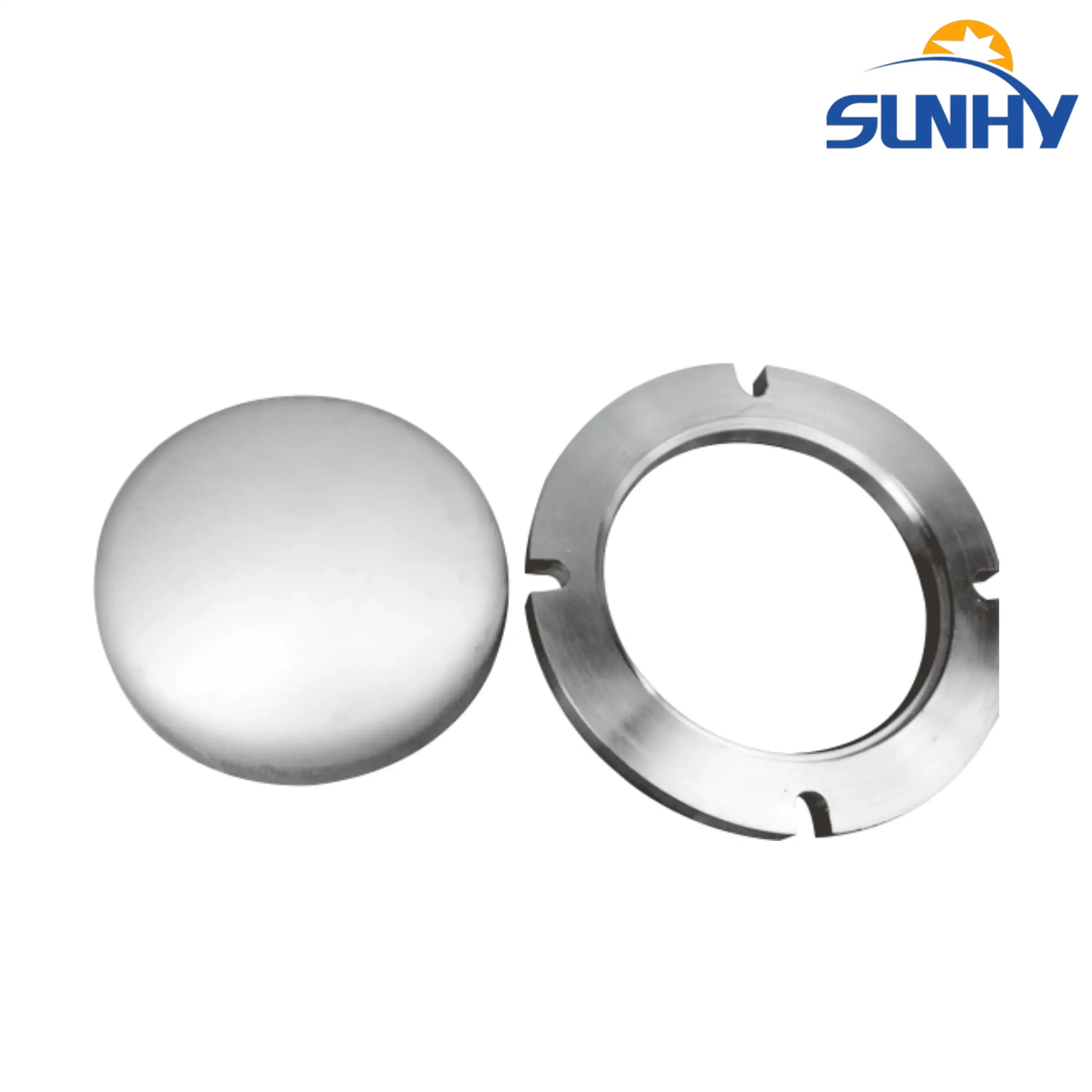
Stainless Steel Milled Groove Flange and Cap Set

Stainless Steel Quick-Install Clamp Flange
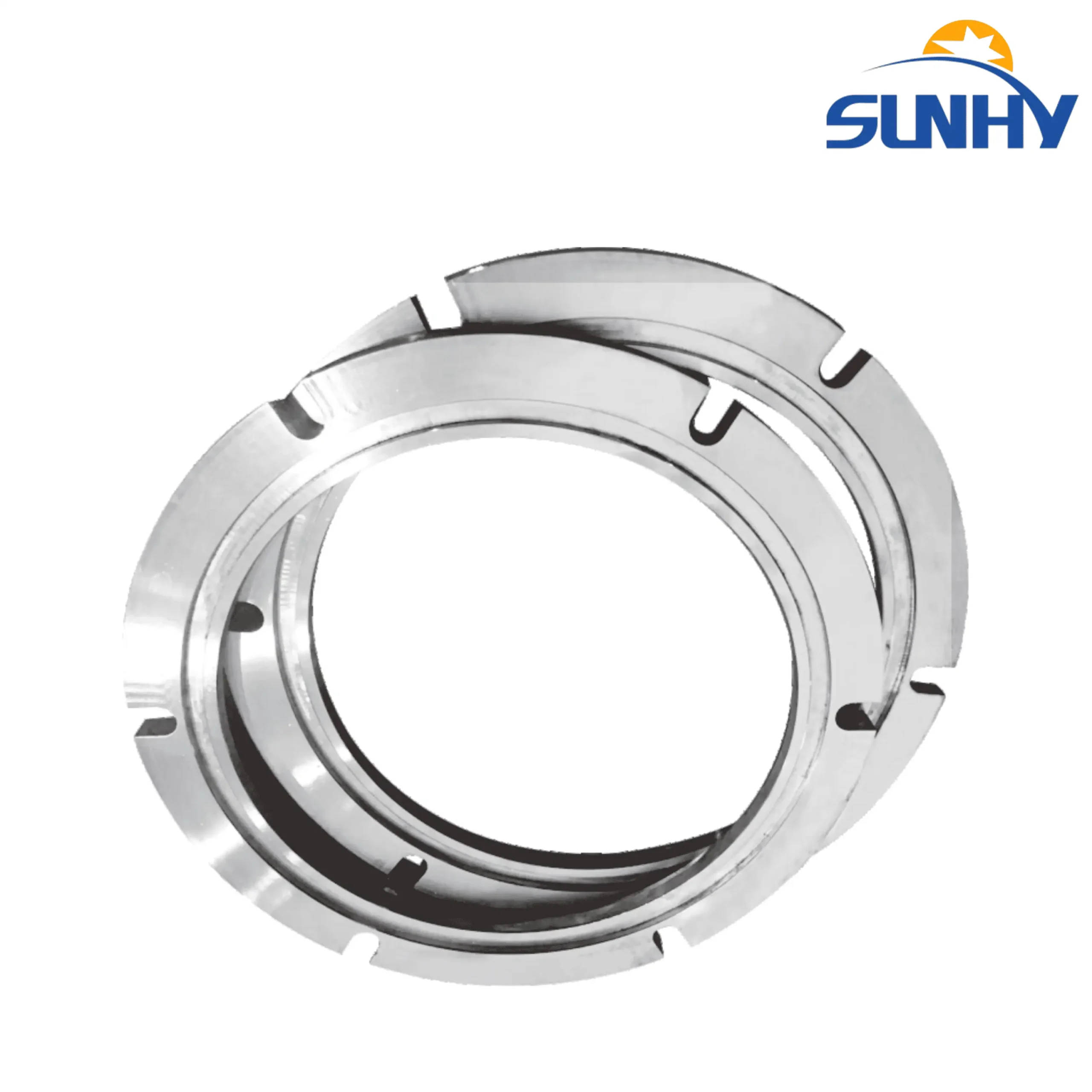
Stainless Steel Quick-Install Milled Flange
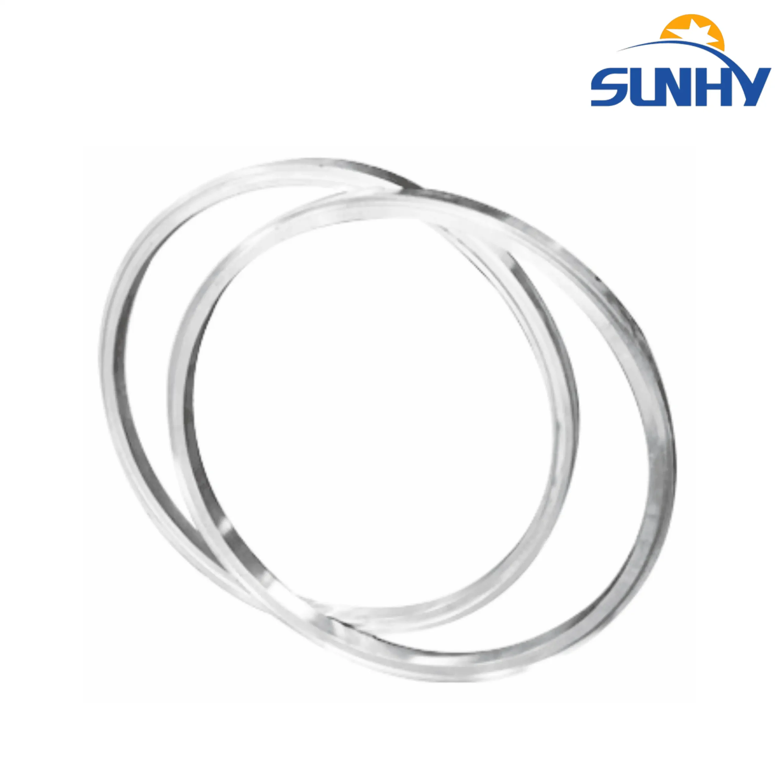
Stainless Steel Filter Ferrule Flange / Rings
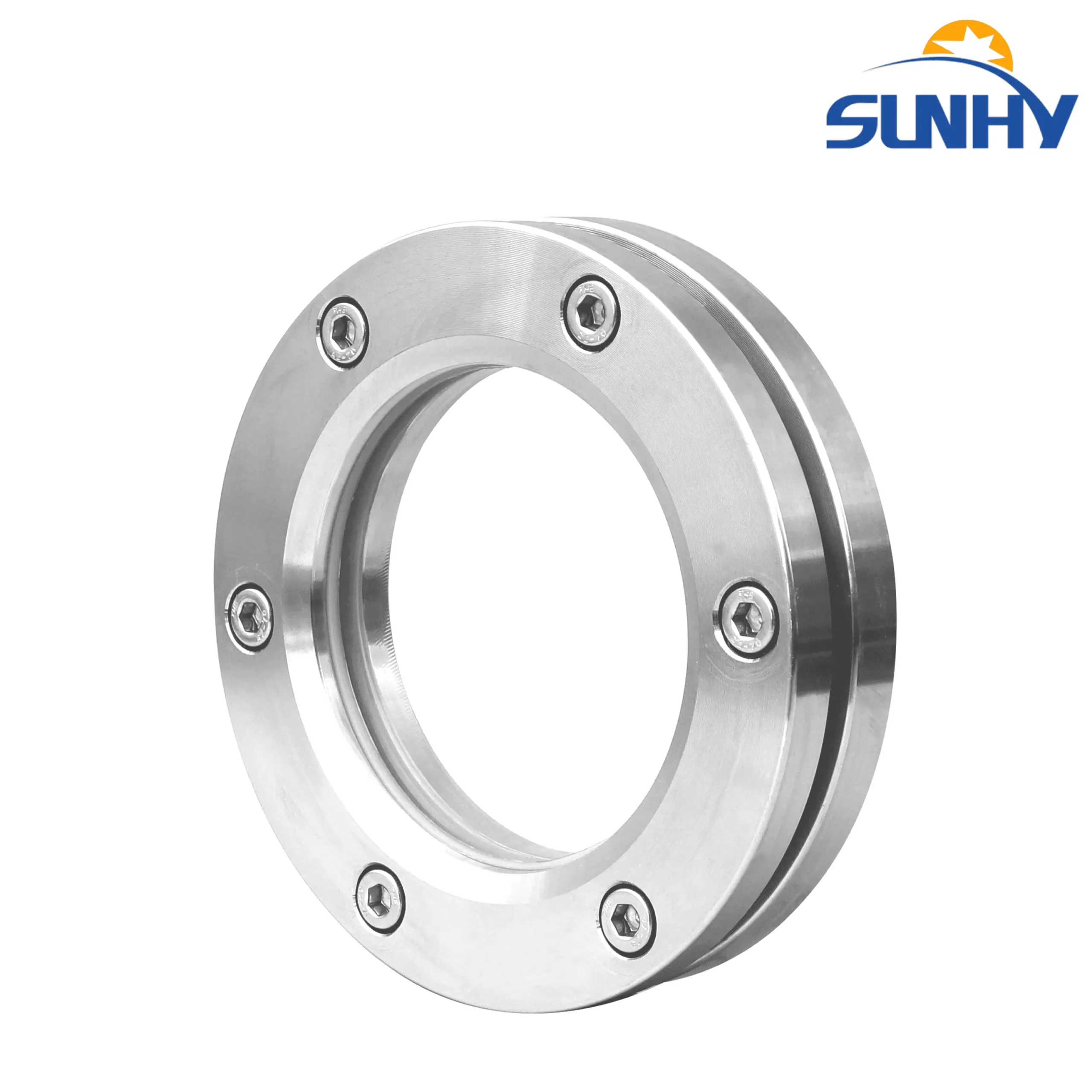
6-Bolt Stainless Steel Sight Glass Flange
Expert Partner: Certified Pressure and Reactor Flange Specialists
Sunhy specializes in manufacturing forged pressure vessel flanges designed to meet the most rigorous industry codes, including ASME Section VIII, ASME B16.5, and ASME B16.47. All products are guaranteed compliant and delivered with 100% material traceability, accompanied by EN 10204 3.1 Material Test Reports (MTRs) to ensure the highest level of quality and safety.
In critical applications, risk management in procurement is essential. Sunhyings is not just a supplier; we are an engineering partner dedicated to helping clients avoid costly mistakes, project delays, and inspection failures.
Sunhyings’ manufacturing capabilities range from standard ASME B16.5 flanges to large-diameter ASME B16.47 Series A and Series B flanges. Furthermore, we possess the expertise to provide custom forged solutions for non-standard dimensions or specialized material grades required in extreme environments (e.g., cryogenic, high-temperature, or corrosive media). With low minimum order quantities (Low MOQ) and highly competitive factory-direct pricing, Sunhyings ensures your project receives the highest standard of product within budget.
What is a Pressure Vessel Flange
The Component and the Flange Connection System
Strictly speaking, a “pressure vessel flange” refers to one component within a complete flange connection system. An intact pressure-retaining flanged connection is a three-part system:
Flanges: Two forged steel rings, typically used in pairs, providing the structural connection.
Gasket: The sealing element located between the two flange faces, which deforms under compression to fill microscopic gaps.
Bolting: A set of high-strength studs and nuts that provide and maintain the necessary compressive load to seat the gasket.
How the Seal Works
The integrity of a flanged joint relies on a precise physical balance. When the installation bolts are tightened, they exert a preload (known as “initial seating stress”) that deforms the gasket material, seating it tightly into the micro-grooves of the flange face to form the initial seal.
When the vessel is pressurized, the internal media creates a “hydrostatic end force” that attempts to pull the flanges apart. The key to a successful flange joint is for the gasket’s resilience and the bolting’s elasticity to work together, maintaining a “working sealing stress” that remains higher than the internal pressure, thereby effectively preventing leaks.
Pressure Vessel Flanges vs. Pipe Flanges
There is a critical distinction between a pressure vessel flange and a standard piping flange. A pressure vessel flange is typically a “Body Flange” or a “Nozzle Flange”. They are designed to be an integral part of the vessel shell, head, or nozzle neck.
Key Difference: Pressure vessel flanges must not only meet the connection standards (like ASME B16.5) but also withstand and transmit the total design stress from the vessel body. Their design and fabrication are governed by the much stricter ASME Boiler and Pressure Vessel Code (BPVC) Section VIII, unlike piping flanges which only follow the pipe code.
Pressure Vessel Flange Technical Specifications
Sunhy manufactures flanges compliant with all major international codes. The table below outlines the key technical parameters required for procurement and engineering design, helping purchasing teams and engineers quickly define their Request for Quotation (RFQ).
| Parameter Specification Detail | Technical Description (High-Value Information) |
| Size Range | NPS 1/2″ to NPS 60″ (DN15 to DN1500) |
| Core ASME Standards | ASME B16.5 (Sizes 1/2″ to 24″), ASME B16.47 Series A / B (Sizes 26″ to 60″) |
| Core European Standard | EN 1092-1 (PN Nominal Pressure system) |
| Core Chinese Standard | GB/T 9124.1 / 9124.2 (PN / Class Series) |
| ASME Pressure Classes | Class 150, 300, 400, 600, 900, 1500, 2500 |
| EN Pressure Ratings | PN6, PN10, PN16…PN400 |
| Common Materials | Carbon Steel (A105), Low-Temp CS (A350 LF2), Alloy Steel (A182 F11, F22), Stainless Steel (A182 F304/L, F316/L) |
| Facing Types | Raised Face (RF), Ring Type Joint (RTJ), Flat Face (FF) |
| Manufacturing Process | Forged Steel (Mandatory for Pressure Vessels) |
| Certification | EN 10204 3.1 Material Test Report (MTR) |
Pressure Vessel Integrity Material Selection Guide
1. Standard and High-Temperature Service: Carbon Steel (ASTM A105)
Use Case: Most common and cost-effective. Used above -29 deg C in non-corrosive environments.
2. Cryogenic and Low-Temperature Service: Low-Temp CS (ASTM A350 LF2)
Use Case: Service where the design temperature is below -29 deg C.
Quality Assurance: Must undergo a Charpy V-Notch Impact Test at -46 deg C (-50 deg F) to prove low-temperature toughness.
3. High-Temperature and Creep Service: Alloy Steel (ASTM A182 F11, F22)
Use Case: High-pressure, high-temperature service in power generation or refineries.
Key Property: Chromium-Molybdenum (Cr-Mo) provides excellent creep resistance at high temperatures.
4. Corrosive Service: Stainless Steel (ASTM A182 F304L, F316L)
Use Case: Chemical reactors, offshore platforms, and systems handling corrosive media.
| Material | Key Property | Selection Criterion |
| F304L | Resists general corrosion. | The “workhorse” stainless steel. |
| F316L | Contains Molybdenum. Provides powerful resistance to pitting and crevice corrosion. | Mandatory selection for aggressive environments (e.g., seawater, chlorides). |
Pressure Vessel Flange Type Procurement Guide
1. Weld Neck (WN) and Long Weld Neck (LWN) Flanges
Application: The preferred choice for all high-pressure, high-temperature, or critical service nozzles.
Rationale: The tapered hub reduces stress concentration. The single butt weld allows for Non-Destructive Testing (NDT), ensuring the highest integrity.
LWN Variant: Often used as a “Body Flange.”
2. Blind Flanges
Application: Used to seal off vessel nozzles, terminate piping systems, or isolate equipment.
Rationale: Must withstand the vessel’s full system pressure (MAWP), critical for Hydro-Testing.
3. Lap Joint Flanges
Application: Suitable for systems handling corrosive media or requiring frequent disassembly.
Rationale: Only the Stub End contacts the fluid (allowing cheaper material for the flange body). The flange rotates freely, allowing easy alignment of bolt holes.
4. Slip-On Flanges
Application: An economic solution for low-pressure, non-critical connections.
Limitations: Significantly weaker than Weld Neck flanges. Not typically used above ASME Class 600 or in cyclically loaded service.
5. Socket Weld (SW) and Threaded (NPT) Flanges
Application: Used exclusively for small-bore (<= 2″) auxiliary connections, such as instrument taps or drains.
Rationale: Avoids butt welds on small piping. Threaded flanges can be used in areas where welding is prohibited.
Manufacturing and Quality
1. Step One: Forging Process (The Foundation of Strength)
Pressure vessel flanges must be forged. Forging refines and aligns the metal’s grain structure, delivering superior strength, toughness, and reliability, while eliminating defects common in casting or plate.
2. Step Two: Quality Control & Non-Destructive Testing (NDT)
Positive Material Identification (PMI): 100% chemical composition verification on all incoming alloy materials.
Non-Destructive Testing (NDT): Includes Ultrasonic Testing (UT) for sub-surface flaws, and Magnetic Particle (MPI) or Liquid Penetrant (LPI) Testing for surface cracks.
3. Step Three: Mechanical Properties and Hydro-Testing
Mechanical Testing: Verification per ASTM A370, including Tensile Tests and Impact Tests (Charpy, mandatory for low-temp materials).
Hydro-Testing: Test pressure is typically 1.3 x the Maximum Allowable Working Pressure (MAWP).
4. Step Four: Final Assurance: EN 10204 3.1 MTR
The EN 10204 3.1 MTR is the final product assurance document. It provides full traceability, chemical composition verification, and mechanical properties verification.
FAQ
Can I use a blind flange machined from steel plate for a pressure vessel?
Yes, you can use a blind flange machined from steel plate, provided it complies with ASME B16.5 Section 5.1. Unlike weld neck flanges which require forging to handle hub stresses, the ASME standard explicitly states that “plate and flat bar materials may be used only for blind flanges and reducing flanges without hubs”.
Key Engineering Considerations:
Material Quality: The plate must meet specifications like ASTM A516 Gr. 70 (Pressure Vessel Quality) to ensure isotropic strength.
Grain Structure: Since blind flanges experience stress primarily perpendicular to the face, the rolled grain structure of high-quality plate is structurally sound for this geometry.
Custom Designs: For sizes or pressures exceeding standard B16.5 ratings, the blind flange must be calculated according to ASME BPVC Section VIII, Div. 1, UG-34.