Эта последняя проверка важна потому, что болт может быть достаточно длинным для сборки, но при этом его резьба или переход между гладким стержнем и резьбой окажется в плоскости среза, где по расчёту предполагается нерезьбовая часть стержня болта. И наоборот, выбор более длинного болта только для того, чтобы увести резьбу от плоскости среза, может создать излишний выступ или помешать правильному наворачиванию гайки. Правильная длина должна удовлетворять обоим условиям.
Описанный ниже метод относится к конструкционным болтам с тяжёлой шестигранной головкой дюймовых серий, применяемым в стальных соединениях, со ссылками на RCSC 2025 Спецификация для конструктивных соединений на высокопрочных болтах. Другие конфигурации крепежа, включая сборки с отрывными головками и контролем натяжения, полностью резьбовые болты и болты со специальной длиной резьбы, требуют собственных проверок размеров.
Определите толщину пакета и набор опорных поверхностей
Толщина пакета — это суммарная толщина соединяемых материалов, зажатых между головкой болта и гайкой. Для простого соединения из двух пластин это сумма толщин двух пластин. Если в соединение входят стыковые накладки или прокладки в пределах зажимаемого узла, их соответствующие толщины также должны быть учтены.
Рассмотрим две стальные пластины: одна толщиной 1/2 in., другая — 5/8 in. Длина зажимаемой части (grip) составляет:
Grip = 1/2 + 5/8 = 1 1/8 in.
Ни высота гайки, ни толщина шайбы в этот показатель не входят. Это различие важно, поскольку метод подбора длины болта по RCSC 2025 начинается с длины зажимаемой части, а затем отдельно учитывает шайбы и дополнительную длину, необходимую для гайки и производственных допусков.
Распространённая ошибка при заказе — начинать с общего размера, который уже включает шайбу, и затем снова добавлять припуск на шайбу. В результате болт может оказаться длиннее, чем предусматривал метод подбора. Противоположная ошибка — измерение только основных соединяемых пластин с пропуском зажатой прокладки — приводит к заниженной длине зажимаемой части.
Схема расположения шайб также имеет значение помимо их суммарной толщины. Шайба под головкой болта отодвигает соединяемую сталь дальше от опорной поверхности головки. Шайба под гайкой увеличивает расстояние, которое гайка должна пройти по болту, но не смещает плоскость среза между пластинами относительно головки болта таким же образом.
Это различие становится существенным, когда проектировщик требует исключить резьбу из плоскости среза.
Перед расчётом длины определите фактический пакет:
- Все соединяемые стальные листы, накладки и применимые прокладки, входящие в зону зажима.
- Количество и тип шайб под головкой болта и гайкой.
- Входит ли в сборку индикатор прямого натяжения, коническая шайба, реакционная шайба или другой специальный компонент.
- Предполагаемая ориентация болта, особенно если соединяемые пластины имеют разную толщину.
Washer requirements are not identical for every structural joint. RCSC 2025 Section 6 addresses washer use under different installation and connection conditions. The actual configuration should come from the project documents and the applicable bolting procedure rather than from an assumed rule that every connection uses one washer in the same location.
В иллюстративном примере пересмотра проекта после выпуска ведомости болтов добавляется пакетная пластина. Заказанный болт может уже не обеспечивать требуемую глубину ввинчивания, поскольку изменилась толщина пакета. Обновите толщины стали и все необходимые несущие компоненты, выберите новую длину-кандидат и проверьте фактическое положение резьбы. Не компенсируйте это исключением предусмотренной шайбы.
Рассчитайте предварительную длину болта исходя из толщины пакета, шайб и припусков под гайку
Для стандартных дюймовых высокопрочных болтов с шестигранной головкой для металлоконструкций, охватываемых руководством RCSC 2025 по выбору длины, первоначальный расчёт можно выразить так:
Пробная длина болта = Толщина пакета + Применимые припуски на крепёж + Добавка к длине в зависимости от диаметра
Эти три члена имеют разное назначение.
Толщина пакета представляет собой толщину соединяемых материалов. Припуски на крепёж учитывают дополнительную толщину указанных шайб или индикаторных устройств. Прибавка к длине в зависимости от диаметра is taken from RCSC 2025 Commentary Table C-2.2 and allows for normal heavy hex nut engagement and manufacturing tolerances in the referenced assembly.
Этот последний термин не следует путать с физической высотой гайки. Это допуск при подборе, а не ещё один компонент, который нужно добавить рядом с отдельным допуском на полную высоту гайки.
For example, the RCSC 2025 Commentary gives a 1 in. length addition for a 3/4 in. nominal bolt diameter. For each standard ASTM F436 washer in the assembly, its stated selection method adds 5/32 in. An extra-thick washer or other approved device has a different allowance, so substituting one washer type for another without revisiting the calculation can change the length selection.
Расчёт для болта 3/4 in. с длиной зажима 1 1/8 in. и одной стандартной шайбой F436 выполняется следующим образом:
Пробная длина = 1 1/8 + 5/32 + 1 = 2 9/32 in.
В десятичном виде:
1.125 + 0.15625 + 1.000 = 2.28125 in.
Согласно процедуре комментария RCSC 2025 этот предварительный результат округляется до ближайшего шага 1/4 in. для болтов длиной не более 6 in. Таким образом, первоначальный вариант составляет 2 1/4 in.
По этой причине трактовка результата как минимума, который всегда нужно округлять в большую сторону, не равнозначна следованию указанному методу комментария RCSC. Не следует также автоматически принимать округлённое значение только потому, что оно является ближайшей номинальной длиной.
Если в соединении используется больше шайб, другой индикаторный прибор или специальный крепёж, его допуск необходимо пересчитать. Если рассматривается более длинный вариант, новую геометрию также необходимо проверить.
Выбранные размеры крепежа должны соответствовать указанному типу болта и требованиям к изделию. ASTM F3125/F3125M распространяется на применимые изделия для конструкционного болтового крепежа, а ASME B18.2.6 устанавливает размерные требования для конструкционного крепежа. Спецификация RCSC регламентирует их применение в конструкционных соединениях. Это связанные, но разные области ответственности; ссылка на один стандарт не заменяет проверку других там, где они применимы.
Проверьте, не попадает ли резьба в плоскости среза
Выбор длины усложняется, когда соединение проектируется с исключением резьбы из плоскости среза.
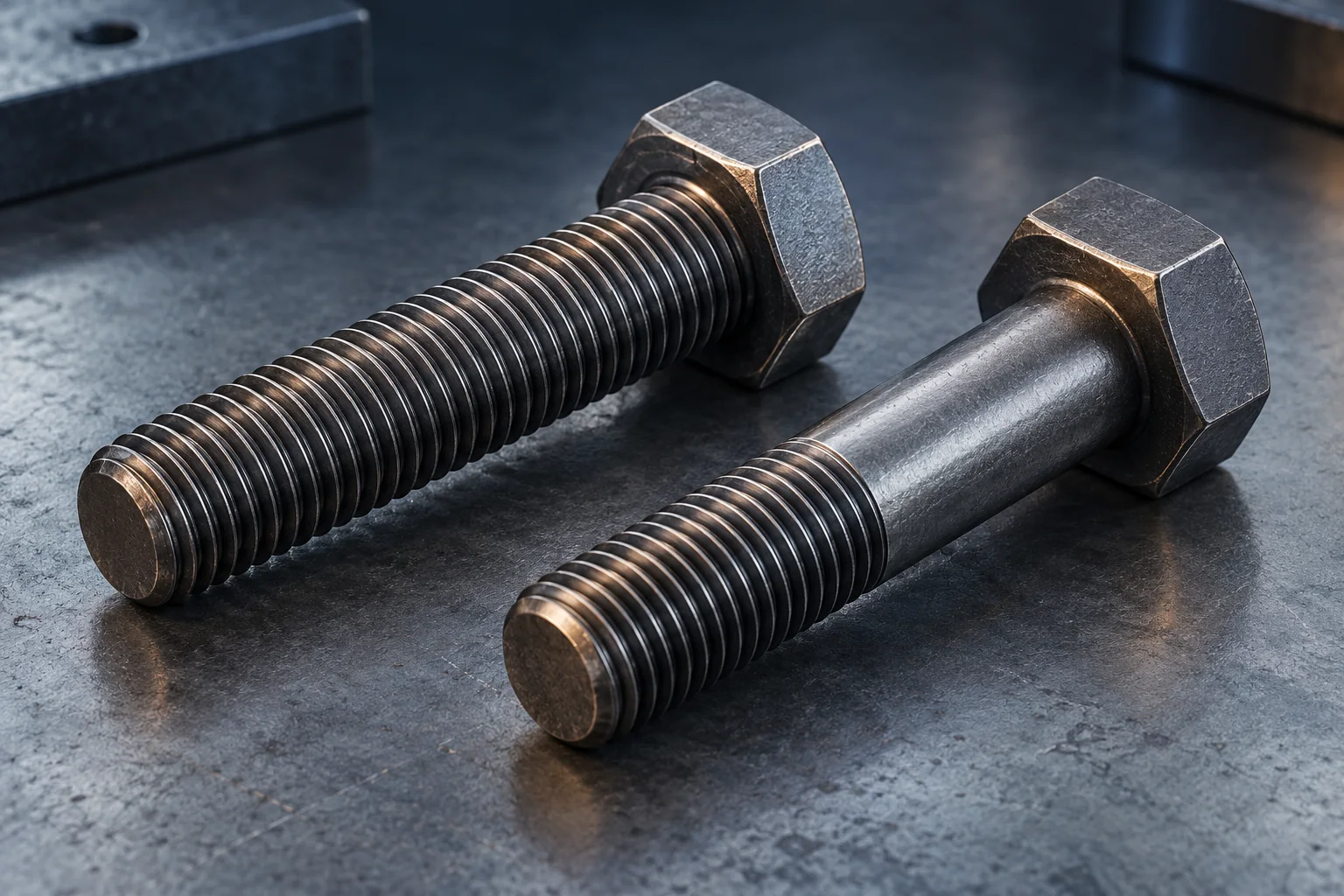
A structural bolt generally has three relevant axial regions: an unthreaded, full-diameter body; a transition region where the thread runs into that body; and the fully threaded portion. Their positions depend on the bolt’s overall length and thread geometry.
For a conventional partially threaded heavy hex structural bolt, let:
- L = nominal bolt length, measured from beneath the head.
- L_T = nominal threaded length measured from the bolt end, as represented in the applicable dimensional reference.
- Y = thread transition length.
Using the nominal geometry illustrated in RCSC 2025 Figure C-2.2, the approximate distance from the underside of the head to the beginning of the thread transition is:
Nominal body-region length = L − L_T − Y
The distance from beneath the head to the beginning of the full-thread region is:
L − L_T
These dimensions serve different checks. Subtracting only the full-thread length ignores the transition region and can overstate the portion of the bolt that is available as an unquestionably unthreaded body.
A shear plane is commonly located at an interface where connected steel elements transfer shear. Its axial position can be measured from beneath the bolt head by adding the thicknesses of any head-side washers and the connected material between the head and that interface.
The resulting shear-plane position can then be compared with the bolt’s actual body and thread geometry.
Threads included versus threads excluded
A structural connection does not universally require the threads to be excluded from the shear plane. Both threads-included and threads-excluded conditions are recognized in structural bolting design, and the applicable assumption determines which shear-resistance provisions the designer uses.
The Engineer of Record must identify where thread exclusion is required. RCSC 2025 Section 1.6 addresses this information in the contract documents, while Section 5.1 provides the corresponding shear-strength framework.
When threads are included, the design must use the applicable threads-included provisions. When they are specified as excluded, the installed assembly must support that assumption. A length-table result alone does not establish it.
The thread transition deserves particular attention. RCSC 2025 Commentary to Section 2.7 explains that earlier treatment of shear planes within this region was less conservative. The current approach requires more care because the transition geometry and permitted manufacturing variations do not justify treating that region as ordinary unthreaded body without further qualification.
This also explains why visually finding a short smooth region on a bolt is not sufficient evidence of threads-excluded performance. Certain short structural bolts are required to be fully threaded under the applicable dimensional rules, and special thread configurations can differ from standard partly threaded bolts. The actual product configuration must be identified before applying a conventional shank-length calculation.
Bolt orientation can change the result
Consider a two-plate connection with unequal plate thicknesses. If the bolt head is on the thinner-plate side, the plate interface is closer to the underside of the head. Reverse the bolt, and that same interface moves farther from the head.
The bolt length, grip and nut configuration may all remain unchanged. Yet the position of the shear plane relative to the unthreaded shank can change.
Adding a washer beneath the bolt head creates a similar effect by moving the steel stack away from the head. A connection initially checked with no head-side washer should not automatically retain its threads-excluded classification after an additional washer is introduced.
This is not merely an installation preference. RCSC 2025 includes requirements related to bolt orientation and notification when head-side washers are added to assemblies whose design depends on thread exclusion.
Where a bolt crosses more than one shear plane, each interface must be considered. RCSC’s design treatment is conservative when threads are present in one of multiple shear planes; it does not simply allow a designer to treat the remaining planes as independently satisfying the more favorable threads-excluded condition.
The practical rule is to evaluate the thread position against the design assumption for the complete connection—not to infer that assumption from the bolt length or the appearance of one shear plane.
Сверьте выбранную длину с фактическим болтовым соединением
The previous calculation produced a 2 1/4 in. candidate. The following hypothetical example shows why it still needs a thread-position check.
Illustrative hypothetical example — not a SUNHY customer project or verified product assembly
Assume a steel connection with:
| Позиция | Assumed dimension or condition |
|---|---|
| Bolt diameter | 3/4 in. |
| Plate adjacent to bolt head | 1/2 дюйма. |
| Plate adjacent to nut | 5/8 in. |
| Total grip | 1 1/8 in. |
| Washer | One standard ASTM F436 washer beneath the nut |
| Head-side washer | Нет |
| Initial bolt length | 2 1/4 in. |
| Alternative candidate | 2 1/2 in. |
For the geometry comparison, the nominal dimensions in RCSC 2025 Commentary Table C-2.1 for the selected diameter are:
- Thread length, L_T = 1 3/8 in.
- Transition length, Y = 1/4 in.
- Heavy hex nut height, H₂ = 47/64 in.
These are reference dimensions, not a complete dimensional tolerance inspection of any manufactured bolt.
Check the 2 1/4 in. candidate
The nominal full-body region ahead of the transition is:
2.25 − 1.375 − 0.250 = 0.625 in.
With the 1/2 in. plate next to the bolt head, the shear plane at the plate interface is 0.500 in. from the underside of the head. It is nominally 0.125 in. before the calculated beginning of the transition.
Now reverse the bolt while keeping the same grip and washer arrangement. The 5/8 in. plate lies next to the bolt head, placing the interface 0.625 in. from the underside of the head.
That position coincides with the nominal start of the transition region.
Therefore, the initial 2 1/4 in. selection cannot be taken as proof that the reversed arrangement meets a threads-excluded design requirement. Permitted dimensional variations and the actual bolt geometry must be considered.
Check the 2 1/2 in. candidate
For the longer bolt, using the same nominal threaded and transition lengths:
2.50 − 1.375 − 0.250 = 0.875 in.
Both possible plate-interface locations—0.500 and 0.625 in. from the head—would lie before the nominal transition region in this simplified geometry.
The longer candidate therefore offers more nominal clearance between the specified shear plane and the transition region. However, that observation does not establish final compliance: actual dimensional tolerances, the applicable bolt configuration and the connection design still control the decision.
Check nut engagement and end projection
The nut-side washer begins beyond the 1.125 in. grip. Adding its 0.15625 in. allowance and the nominal nut height of 47/64 in. gives a nominal distance to the outside face of the nut of:
1.125 + 0.15625 + 0.734375 = 2.015625 in.
Assuming full seating of the specified components, the nominal bolt-end projections would be:
- 2 1/4 in. bolt: 2.250000 − 2.015625 = 0.234375 in.
- 2 1/2 in. bolt: 2.500000 − 2.015625 = 0.484375 in.
The arithmetic establishes the geometric difference between these two candidates. It does not, by itself, demonstrate compliant thread engagement or prescribe an allowable end projection. The nut must engage the actual threaded section without being stopped by the runout, and any relevant installation or clearance requirements must still be checked.
This example produces a useful selection distinction: the 2 1/4 in. bolt is the initial result of the length-selection method, while the 2 1/2 in. candidate provides a different nominal thread-position relationship. Which candidate is acceptable depends on the approved design, the actual bolting components and the required assembly configuration.
If the design requires thread exclusion, changing bolt orientation, washer location or the selected length cannot be treated as an informal field adjustment. The revised arrangement needs to remain consistent with the connection drawings and applicable engineering requirements.
A hypothetical trial assembly has acceptable nut engagement, yet a shear plane lies in the thread transition rather than the assumed smooth shank. Nominal overall length did not establish usable body length. Check the actual geometry and orientation against the approved shear assumption. The bolt measurement procedure supports identification; the connection drawing supplies the acceptance basis.
Укажите длину в спецификации конструкционных болтов или в запросе предложения
After completing the geometric checks, translate the selection into information that a supplier and fabricator can use without having to guess which assembly was intended.
A structural bolt specification should identify the nominal diameter and length, applicable product grade, type and style, required standards and their governing editions, and the corresponding nut and washer configuration. The coating or finish also needs to be identified because the components must form an appropriate compatible bolting assembly.
For a connection whose design depends on thread exclusion, the bolt schedule or accompanying connection documentation should also make the design assumption, required orientation and relevant washer positions clear. Listing only the diameter and overall length may not be enough to preserve the verified shear-plane arrangement.
For the hypothetical example, an incomplete purchasing description would simply say:
3/4 in. × 2 1/4 in. structural bolt
That does not establish the product grade or thread configuration, and it gives no indication that bolt orientation may affect the intended shear-plane condition.
A more useful purchasing record would identify the engineer-approved length together with the complete component specification and a reference to the connection detail showing the required installation arrangement. Any dimensional or inspection evidence requested from the supplier should be tied to the actual specified product and contract requirements.
Where a standard catalog length cannot satisfy both the necessary thread position and normal nut engagement, the decision may require review of washer arrangements, bolt orientation or an expressly approved special thread configuration. It should not be resolved by assuming that every available bolt of the same nominal diameter has the same usable shank geometry.
The final selection is not simply the nearest bolt length from a calculation. It is the length whose assembled geometry supports the specified connection design, including adequate nut engagement and the required relationship between the bolt threads and shear planes.
Technical basis
The principal reference for the selection method and thread-position discussion is the RCSC Specification for Structural Joints Using High-Strength Bolts (June 5, 2025), particularly the requirements and commentary concerning component geometry, bolt-length selection, washer arrangements and shear-plane design. The relevant structural fastener dimensional standard is ASME B18.2.6, as referenced by RCSC. Specific procurement and engineering acceptance must follow the governing project documents and applicable standard editions.
Часто задаваемые вопросы
Входит ли головка болта в длину зажима?
№. Толщина захвата — это толщина соединяемого зажимаемого материала. Необходимые шайбы и другие крепёжные элементы учитывайте отдельно, используя основной метод подбора длины.
Достаточна ли длина зацепления гайки как единственная проверка?
Нет. Также проверьте шайбы, сбег резьбы, полезную длину стержня, ориентацию болта и принятое в расчёте допущение о расположении резьбы в каждой плоскости среза.
Можно ли снять шайбу, чтобы короткий болт подошёл?
Только если утверждённые требования к соединению и монтажу допускают изменённую схему. В противном случае используйте болты правильной длины и необходимые комплектующие.