Butt Weld Reducer Manufacturer | ASME B16.9 | Concentric Reducer & Eccentric Reducer | Smooth Pipe Size Transition
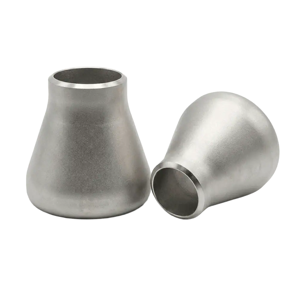
SUNHY supplies butt weld reducers for welded piping systems that require a clean flow path and reliable size transition. We offer both concentric reducers (centered reduction) and eccentric reducers (flat-side reduction) to match your piping layout, drainage needs, and installation orientation.
Factory-direct supply with consistent weld-end preparation, dimensional control, and project-ready documentation—ideal for process lines, utilities, water treatment, HVAC, and general industrial piping.
- Smooth size transition for stable flow
- Simplifies spool layout and pipe routing
- Fit-up friendly for faster welding work
- Reduces field rework and alignment risk
- Clear marking & traceability for receiving
- Docs/inspection available per project needs
Specification & Standard
Nominal Diameter (DN / NPS)
DN 15 – DN 600 (NPS 1/2″ – 24″); larger sizes on request
Reducer Type
Concentric Reducer / Eccentric Reducer
Size Configuration
Run × Outlet (e.g., 10″ × 8″, 8″ × 6″)
Standards
ASME B16.9 / EN 10253 / GB/T 12459 (per project requirement)
End Preparation
Beveled ends for butt welding (per project WPS)
Wall Thickness (Schedule)
Sch 10 / Sch 40 / Sch 80 / STD / XS / customized thickness
Materials
ASTM A403 (304/316L) / ASTM A234 WPB (others on request)
Documentation & Inspection
MTC (EN 10204 3.1), dimensional inspection; PMI for stainless upon request; NDT as specified
Butt Weld Reducers | Concentric Reducer & Eccentric Reducer | ASME B16.9
SUNHY supplies butt weld reducers designed for reliable pipe size transitions in welded piping systems. We provide both concentric reducers for centered reduction and eccentric reducers for flat-side reduction, helping you control alignment, drainage, and installation orientation in real piping layouts.
Reducers are commonly specified by Run × Outlet size, schedule (wall thickness), and weld-end preparation. We support project documentation and traceability for procurement, QA inspection, and site acceptance.
Key Advantages
- Smooth Size Transition — Maintains stable flow with a clean internal profile in welded spools.
- Two Geometry Choices — Concentric for symmetric reduction; eccentric to manage air pockets or drainage.
- Schedule & Fit-Up Control — Common schedules plus customized thickness based on line class.
- Project-Ready Documentation — MTC/EN 10204 3.1 and heat number traceability available upon request.
Technical Summary
| ITEM | SPECIFICATION |
|---|---|
| Product Type | Butt Weld Reducer (Concentric Reducer / Eccentric Reducer) |
| Nominal Size | DN 15 – DN 600 (NPS 1/2" – 24"); larger sizes available by request |
| Size Format | Run × Outlet (e.g., 10" × 8", 8" × 6") |
| Wall Thickness | Sch 10 / Sch 40 / Sch 80 / STD / XS (customized thickness available) |
| End Preparation | Beveled ends for butt welding (per project WPS) |
| Standards | ASME B16.9 / EN 10253 / GB/T 12459 (as specified) |
| Documentation | MTC (EN 10204 3.1), dimensional inspection; PMI/NDT available on request |
Reducer Dimensions | Concentric Reducer vs Eccentric Reducer | ASME B16.9
A reducer is defined by the large end (Run) and small end (Outlet) sizes and the end-to-end length specified by the applicable standard (commonly ASME B16.9). A concentric reducer is symmetric on the centerline, while an eccentric reducer has an offset to create a flat side for drainage or to reduce air pocket risks.
What Engineers Typically Confirm
- D1 / D2: large-end OD and small-end OD (by pipe size/spec)
- H: end-to-end length (per ASME B16.9 or project standard)
- t: wall thickness (schedule)
- e: eccentric offset (eccentric reducers only)
Quick Selection Guide
| Type | Best For | Key Check | Common Note |
|---|---|---|---|
| Concentric Reducer | Vertical lines, centered alignment | Run × Outlet + H per standard | Symmetric reduction on centerline |
| Eccentric Reducer | Horizontal lines, drainage control | Orientation + offset e + H per standard | Flat side up/down depending on service |
If you need a BOM-ready dimensional list, send your Run × Outlet sizes and schedule, and we can confirm the applicable standard dimensions for your project.
Related Products
Butt Weld Tee (Equal / Reducing)
For branch connections in welded piping spools.
Concentric Reducer
Smooth centerline transition for vertical lines and pumps.
Eccentric Reducer
Flat side design to reduce air pockets in horizontal piping.
Butt Weld End Cap
Clean closure for pipe ends—ideal for test spools and headers.
Stub End (Lap Joint)
Common with lap joint flanges for frequent disassembly service.
FAQ
What’s the difference between a concentric reducer and an eccentric reducer?
The primary difference is the alignment of their centerlines. A concentric reducer is symmetrical (cone-shaped), aligning the centerlines of both the larger and smaller pipes, which makes it ideal for vertical flow applications. An eccentric reducer is asymmetrical with one flat side parallel to the flow direction, offsetting the centerlines. This “flat side” design allows for proper drainage or air removal in horizontal piping systems.
How do I choose “flat side up” or “flat side down” for an eccentric reducer?
The orientation depends on the fluid type and the piping function to prevent system failure:
Pump Suction (Standard): Install Flat Side Up (FSU). This prevents air bubbles from accumulating at the top of the reducer, which could enter the pump and cause cavitation.
Pump Suction (Supply from Above): Install Flat Side Down (FSD). If the flow comes vertically downwards into the suction, FSD allows trapped air to bleed back up the line.
Slurries/Solids: Install Flat Side Down (FSD). This provides a continuous bottom surface, preventing solid debris from piling up behind the reducer dam.
Steam/Gas Lines: Install Flat Side Down (FSD). This allows liquid condensate to drain freely at the bottom, preventing water hammer or corrosion.
What size format should I provide when ordering a butt weld reducer?
When ordering, you must strictly follow the x format. Do not simply specify the reducer size; you must also specify the schedule (wall thickness) for both ends if they differ.
Correct Specification Example: Reducer, Eccentric, 4″ x 2″, Schedule 40 x Schedule 80, ASTM A234 WPB, ASME B16.9.
Critical Note: The length of the reducer is standardized based on the large end size, so you do not need to specify length unless non-standard dimensions are required.
Do reducer schedules need to match the pipe schedule?
Yes, for the best integrity, the reducer’s wall thickness (schedule) should match the mating pipe at each end. However, if a thicker reducer is used on a thinner pipe, the reducer bore must be tapered (machined) on the inside diameter.
Expert Requirement: According to ASME B31.3, this taper must be at a slope of 1:3 (approx. 18° to 30°) to smooth the transition and minimize stress concentration factors (SCF) at the weld root.
Which standards are commonly used for butt weld reducers?
The two dominant standards used globally are:
ASME B16.9: This is the industry standard for factory-made wrought butt-welding fittings sized NPS ½ to NPS 48. It governs dimensions, tolerances, and testing methods.
MSS SP-75: This standard is used for high-test, wrought, butt-welding fittings, typically for high-pressure oil and gas transmission pipelines. It covers larger sizes (NPS 16 to NPS 60) and includes rigorous fracture toughness testing.