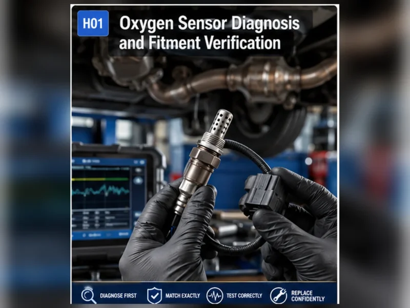
Guía técnica del sensor de oxígeno
Comprenda qué identifican los códigos comunes de sensor de oxígeno P0130-P0167, por qué P0420 es diferente y qué verificaciones de circuito y sistema deben realizarse antes del reemplazo.
Respuesta rápida
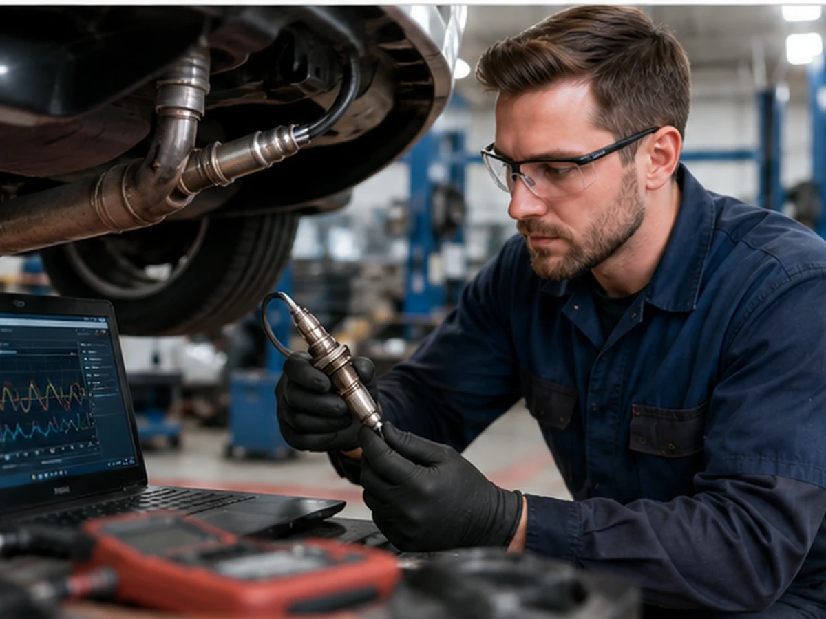
Los códigos P0130-P0167 generalmente identifican un circuito de sensor de oxígeno, calentador, actividad o condición de respuesta para un banco y sensor determinados. No demuestran que el elemento sensor esté defectuoso. Diagnostique cableado, conectores, alimentación y tierra, fugas de escape, condiciones de mezcla y datos en vivo. P0420/P0430 se refieren a la eficiencia del sistema de catalizador y no deben tratarse como códigos automáticos de reemplazo del sensor de oxígeno.
Familias de códigos y la pregunta que cada una plantea
| Familia de ejemplo | Significado general | Primera pregunta de diagnóstico |
|---|---|---|
| P0130 / P0150 | Fallo en el circuito del sensor | ¿El circuito de señal está intacto y la condición del motor es plausible? |
| P0131-P0132 / P0151-P0152 | Señal baja o alta | ¿Es esto un límite eléctrico, una condición de mezcla real o contaminación? |
| P0133 / P0153 | Respuesta lenta | ¿Las condiciones de operación son correctas y hay fugas o fallos de combustible que ralentizan la transición observada? |
| P0134 / P0154 | No se detectó actividad | ¿El sensor está caliente, alimentado y conectado, y la señal llega al módulo? |
| P0135 / P0141 / P0155 / P0161 | Fallo del circuito del calentador | ¿Están dentro de las especificaciones la alimentación, masa, fusible, control y resistencia del calentador? |
| P0420 / P0430 | Eficiencia del catalizador por debajo del umbral | ¿Son válidas las condiciones del motor, escape, datos del sensor y del catalizador? |
La definición exacta y los criterios de habilitación varían según el fabricante. Siempre lea la descripción completa, los datos de congelación de imagen y el procedimiento de servicio del vehículo.
Decodifique Bank y Sensor antes de tocar una pieza
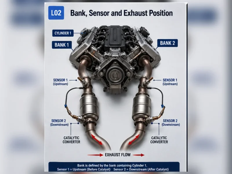
El banco 1 contiene el cilindro 1; el banco 2 es el banco opuesto cuando está presente. El sensor 1 está comúnmente antes del catalizador y el sensor 2 después. No use una regla universal del lado del conductor. Un diagnóstico correcto en el sensor físico equivocado sigue siendo una reparación incorrecta.
Un orden de diagnóstico de seis pasos
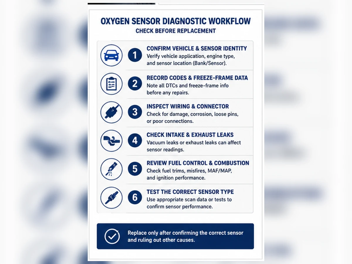
- Registre todos los códigos actuales, pendientes y permanentes, además de la congelación de imagen.
- Confirme el banco exacto, el sensor y la tecnología.
- Inspeccione el enrutamiento del arnés, el estado del conector y las fugas de escape.
- Pruebe la alimentación, la masa y el control del calentador cuando el código se refiera a la calefacción.
- Revise los trimados de combustible y el voltaje, la corriente o lambda del sensor según lo especificado.
- Repare la causa raíz y verifique el monitor sin dispositivos de derivación.
Por qué P0420 y P0430 requieren cuidado especial
Estos códigos evalúan el comportamiento del sistema catalizador utilizando varias condiciones y señales de sensores. Las fugas de escape, los fallos de encendido, los problemas de control de combustible, el sesgo del sensor y el deterioro del catalizador pueden afectar el resultado. Reemplazar un sensor aguas abajo sin validar su señal y el resto del sistema puede desperdiciar la oportunidad de reparación.
Acciones que no completan el diagnóstico
Borrar el código, desconectar la batería, instalar un espaciador o simulador, o reemplazar sensores repetidamente no establece la causa. Los controles de emisiones deben repararse cumpliendo con la ley aplicable. Utilice la información de código permanente y de preparación para verificar el proceso de reparación legal.
Lea cada DTC como sistema, posición y modo de falla
Una descripción completa del código combina el sistema monitoreado, la posición del banco/sensor y el modo de falla, como circuito bajo, circuito alto, sin actividad, respuesta lenta o fallo del calentador. El código indica qué ruta de prueba abrir. No identifica el sensor reemplazable como el punto de falla ni proporciona un número de pieza.
| Elemento del código | Pregunta respondida | Pregunta no respondida |
|---|---|---|
| Banco 1 / Banco 2 | ¿Qué banco del motor se monitorea? | Lado físico universal |
| Sensor 1 / Sensor 2 | Posición común pre/post catalizador | Conector exacto sin diagrama de servicio |
| Actividad baja/alta/sin actividad | Condición de señal detectada | Sensor versus cableado versus mezcla real |
| Circuito calefactor | Criterio de monitorización de ruta de calentamiento fallido | Elemento versus fusible/alimentación/tierra/control |
Significado diagnóstico de familias de códigos comunes
Fallo de circuito, códigos bajos y altos
P0130/P0150 y códigos relacionados de bajo/alto requieren comprobaciones de circuito y plausibilidad. Inspeccione los circuitos de señal y referencia, el estado del terminal y la evidencia de escape/mezcla. Un valor bajo puede reflejar una condición real de mezcla pobre; un valor alto puede reflejar una operación rica. Los límites eléctricos y las especificaciones de servicio controlan la distinción.
Respuesta lenta y sin actividad
P0133/P0153 y familias de sin actividad requieren temperatura de operación válida y criterios de habilitación. Verifique el funcionamiento del calentador, fugas, respuesta real de la mezcla y tasa de datos del escáner. Un PID plano no soportado no es prueba de un sensor muerto.
Códigos de calentador
P0135, P0141, P0155, P0161 y códigos relacionados abren una ruta del circuito del calentador. Pruebe la alimentación protegida, fusible, tierra/control, conector, arnés y elemento según el diagrama. La resistencia por sí sola no demuestra que se suministre potencia bajo carga.
Conserve la evidencia de fotograma congelado y preparación
Registre los códigos actuales, pendientes y permanentes antes de borrar. La imagen congelada muestra el estado del motor cuando el monitor detectó una falla y puede revelar contexto de arranque en frío, ralentí, carga o velocidad. El estado de preparación indica qué monitores se han completado. Borrar códigos elimina contexto útil y reinicia monitores, por lo que no debe ser la primera acción de diagnóstico.
| Registro | Por qué mantenerlo | Error común |
|---|---|---|
| Todos los códigos | Muestra patrones de potencia compartida, mezcla o fallo de encendido | Centrarse solo en un código de O2 |
| Fotograma congelado | Define las condiciones de detección | Borrar antes de guardar |
| Preparación | Muestra la finalización del monitor | Asumiendo que sin luz significa que todas las pruebas pasaron |
| DTC permanente | Requiere reparación confirmada por el monitor | Intentando borrarlo manualmente |
Confirme el circuito físico nombrado por el código
El banco 1 contiene el cilindro 1. El sensor 1 generalmente está antes del catalizador y el sensor 2 después. No use una regla universal del lado del conductor. Haga coincidir el código con el diagrama de escape y el enrutamiento del conector. Probar el sensor incorrecto puede producir mediciones técnicamente correctas para el circuito equivocado.
Seis comprobaciones antes de decidir sobre una pieza
- Confirme la definición del código y los criterios de habilitación para el vehículo exacto.
- Identifique el banco, la posición y la tecnología del sensor.
- Inspeccione el conector, los terminales, el enrutamiento del calor y las fugas de escape.
- Test heater and signal circuits with the correct diagram.
- Compare fuel trims, commanded state and sensor response.
- Repair the root cause and verify the monitor legally.
| Failure mode | First physical check | Required system check |
|---|---|---|
| Heater | Harness, connector and protected supply | Control/ground under specified conditions |
| Low/high signal | Signal/reference integrity | Actual rich/lean condition and leaks |
| No activity | Connection and heater operation | Supported PID and operating temperature |
| Respuesta lenta | Contamination and exhaust integrity | Controlled technology-specific response |
P0420/P0430 son una ruta separada del sistema de catalizador
These codes evaluate catalyst-system efficiency using upstream/downstream behavior under defined conditions. They can be influenced by catalyst deterioration, exhaust leaks, misfire, fuel-control problems and sensor bias. They are not in the P0130-P0167 sensor-circuit family and should not be converted into a downstream-sensor order without validation.
Elija herramientas según la pregunta
Herramienta de escaneo
Use it for codes, freeze frame, readiness, trims and supported sensor data. Confirm units and sample rate. A graph still needs known operating conditions.
Multimeter and oscilloscope
Use a meter for specified power, ground, continuity or resistance checks and an oscilloscope where waveform detail is required. Avoid probing methods that spread terminals or damage wideband circuits.
Leak and mechanical checks
Intake or exhaust leaks, fuel delivery, ignition and engine condition can create the reported exhaust behavior. Use safe, application-appropriate methods and repair these conditions before condemning the reporter.
Escenario compuesto: un código de calentador sobrevive al reemplazo del sensor
Escenario de diagnóstico compuesto: a new sensor is installed for P0141, but the code returns. The correct wiring diagram and loaded test show missing supply at the connector due to heat-damaged wiring. Repairing and rerouting the harness restores the circuit. This composite example is not a Sunhyings case or evidence for a specific vehicle.
Verifique el monitor original, no solo la luz de advertencia
After repair, confirm physical routing, circuit function and plausible live data. Complete the manufacturer’s required monitor conditions safely and legally. A permanent code may remain until the monitor passes. Battery disconnection, repeated clearing, spacers, simulators or software defeat do not prove repair and can interfere with emissions compliance.
Cree un registro de reparación que pueda resistir una reclamación
Save the original code status, freeze frame, circuit readings, leak or mixture findings, physical position, repaired component and post-repair data. Include connector and routing photos when heat or intermittent movement was involved. If the code returns, this record prevents the diagnostic process from restarting with another unsupported sensor replacement.
For a parts return, add the OE/application basis, delivered part and lot, installation position and vehicle-side circuit results. A returned sensor cannot be judged fairly when the seller receives only the code number. Separate catalog error, installation damage, unresolved root cause, vehicle wiring and product nonconformance.
When several oxygen-sensor codes appear together
Look for shared supplies, grounds, harness damage or system-wide rich/lean conditions before treating each code as an independent failed sensor. Multiple heater codes can point to a protected supply; multiple mixture-related codes can point to air, fuel or exhaust causes. The wiring diagram and complete code set determine whether the faults share a path.
A code that changes from current to history or disappears after clearing has not necessarily passed its monitor. Record how status changes through the specified drive conditions and whether readiness completes. Intermittent heat or vibration faults may require observation through warm-up and harness movement using safe methods. Verification must reproduce the monitor’s question, not merely produce a clean dashboard.
Cómo leer un DTC de sensor de oxígeno sin convertirlo en un pedido de piezas
An OBD-II code names a monitored circuit, signal behavior or system result. It does not contain the sensor technology, connector, lead length, thread, calibration or verified replacement number. Begin by writing the complete code description, status and freeze-frame conditions. Then map Bank and Sensor identity using service information before touching a connector.
The familiar P0130-P0167 range includes signal-circuit, low/high voltage, slow response, no activity and heater-circuit concerns across two banks and two sensor positions. Manufacturer-specific codes and wideband/A/F strategies can use different descriptions and tests. The code family is a routing index, not a universal test specification.
| Code family | Monitor concern | Checks before replacement | Common false conclusion |
|---|---|---|---|
| P0130 / P0150 | Sensor 1 circuit malfunction | Connector, signal/reference circuits, exhaust leaks, mixture state and response | “Circuit” always means the sensing element is open |
| P0131 / P0151 | Sensor 1 low indication | Actual lean condition, signal short, reference integrity and pre-sensor leak | Low voltage always proves a lean-running engine or bad sensor |
| P0132 / P0152 | Sensor 1 high indication | Actual rich operation, signal short, fuel pressure, injector and purge evidence | High voltage always means the sensor is stuck |
| P0133 / P0153 | Respuesta lenta | Operating temperature, exhaust leaks, contamination, test conditions and circuit | One slow scan graph proves aging |
| P0134 / P0154 | No detected activity | Enable conditions, heater operation, signal/reference circuits and data support | A flat value always comes from the sensor |
| P0135 / P0155 | Sensor 1 heater circuit | Fuse, loaded supply, control/ground, connector and specified resistance/current | Every heater code requires a sensor |
| P0136 / P0156 | Sensor 2 circuit malfunction | Rear harness exposure, connector, circuit integrity and exhaust condition | A rear circuit code is a catalyst verdict |
| P0137 / P0157 | Sensor 2 low indication | Signal circuit, leaks, actual mixture and monitor conditions | Replace the rear sensor without checking exhaust leakage |
| P0138 / P0158 | Sensor 2 high indication | Signal short, actual rich condition, contamination and circuit | A fixed rich value proves catalyst failure |
| P0139 / P0159 | Sensor 2 slow response | Exact monitor procedure, temperature, leaks and sensor/circuit response | Compare the rear sensor directly with front switching at all times |
| P0140 / P0160 | Sensor 2 no activity | Enable conditions, signal path, connector and heater operation | No visible switching is always abnormal for a rear sensor |
| P0141 / P0161 | Sensor 2 heater circuit | Protected power, control/ground, connector and harness near exhaust | Replace first and test the circuit later |
Los códigos actuales, pendientes y permanentes responden a diferentes preguntas
A current or confirmed code indicates the monitor has met its confirmation logic. A pending code can preserve an early failure before confirmation. A permanent code is retained under regulated OBD logic until the system observes the required successful operation; it is not necessarily evidence that the repair failed immediately after parts replacement. Definitions and clearing behavior vary by regulation and vehicle strategy, so use the scan-tool and service information correctly.
| Registro | What it contributes | What it cannot prove |
|---|---|---|
| Code status | Whether the fault is pending, confirmed or retained as permanent | Which physical component caused the condition |
| Fotograma congelado | Load, speed, temperature and other captured conditions at failure | Every change that occurred before or after the capture |
| Preparación | Whether relevant monitors have completed since reset or repair | That an incomplete system has passed |
| Mode 6 or monitor data | Manufacturer-supported monitor results and limits where available | A universal diagnosis without correct test identification and scaling |
| Live data | Behavior during controlled operating states | Cause without circuit, engine and exhaust context |
Ruta de decisión para código de calentador
The heater brings the sensing element to operating temperature and helps maintain it at low exhaust flow. Depending on design, the control module may monitor resistance, current, voltage or time-to-activity. Start with the correct diagram and pin identification. Check the fuse or shared supply, but do not stop at continuity. A corroded connection can pass a low-current meter test and fail under heater load.
- Confirm the code names the exact bank, sensor and heater circuit.
- Inspect the harness from connector to protected loom, especially near shields and moving components.
- Verify supply and control or ground under the specified conditions and load.
- Measure sensor-side resistance or current only with the specified temperature and limits.
- Check shared circuits and related codes before replacing an isolated part.
- After repair, confirm heater operation and monitor completion rather than only clearing memory.
Ruta de decisión para código de señal
For low, high, slow or no-activity codes, establish whether the control module is seeing a real exhaust condition. Inspect for leaks ahead of the sensor and compare fuel trims, airflow, coolant temperature, fuel pressure and misfire evidence. Prove signal and reference integrity. Then apply a technology-correct rich/lean or response test under the required temperature and operating conditions.
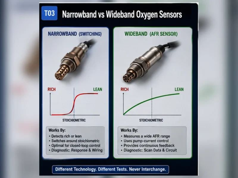
Do not back-probe or apply voltage unless the service procedure permits it. Wideband control circuits can be damaged or misinterpreted by narrowband test habits. A graphing meter or scan tool is useful only when its data item, scale and sample rate are understood.
P0420 y P0430 son códigos de eficiencia del sistema catalizador
P0420 and P0430 indicate that the catalyst monitor has evaluated efficiency below its calibrated threshold for the named bank. The monitor uses oxygen-sensor information, but the code does not say “replace the downstream oxygen sensor.” Misfire, mixture control, oil or coolant contamination, exhaust leakage, incorrect sensors, calibration issues and catalyst condition can all matter. Diagnose related faults first and follow the manufacturer catalyst-monitor procedure.
| Evidencia | Por qué es importante | Límite |
|---|---|---|
| Related misfire or fuel-control codes | They can damage or distort catalyst performance | Repairing them does not automatically prove catalyst health |
| Exhaust leak inspection | Outside oxygen can change sensor behavior | A visual check may miss a leak that opens hot |
| Correct sensor identity | Wrong technology or position can invalidate monitoring | A connector that fits is not calibration proof |
| Upstream/downstream data | Supports monitor analysis under valid conditions | One idle screenshot is not a complete catalyst test |
| Oil/coolant consumption evidence | Contamination can affect sensor and catalyst | Deposit color alone is not a laboratory analysis |
Caso compuesto: dos códigos de calentador y una falla de suministro compartido
Composite engineering scenario: two sensors on different banks set heater codes after underbody work. Replacing one sensor does not change either code. The wiring diagram shows a protected supply shared by both heaters. A loaded voltage test finds a high-resistance connection at a disturbed junction. Repair restores current to both circuits and the monitors complete.
The important clue is the common failure pattern. Two parts can fail, but a shared circuit deserves examination before two independent components are ordered. This is a composite diagnostic example, not a Sunhyings customer case.
Caso compuesto: un pedido de sensor trasero fue detenido por evidencia anterior
Composite engineering scenario: a vehicle presents P0420 with no oxygen-sensor circuit code. The proposed repair is a downstream sensor because its graph moves. Review finds intermittent misfire history and excessive fuel correction on the monitored bank. The team corrects the engine fault, verifies exhaust sealing and reruns the catalyst monitor before making a catalyst or rear-sensor decision.
A moving rear signal is not by itself proof of a failed rear sensor, and a stable rear signal is not universal proof of a good catalyst. The monitor’s enable criteria and vehicle procedure control the interpretation. This scenario is composite and contains no claimed repair rate or customer identity.
Crear un registro de prueba de DTC que sobreviva al traspaso
A code diagnosis often moves between a driver, parts counter, workshop and supplier. Each handoff can lose context. Use a compact record that links the code to the physical circuit and the conditions under which it failed. Screenshots without vehicle identity or data-item labels are weak evidence; values without units or operating conditions can be worse than no data.
| Campo de registro | Minimum content | Razón |
|---|---|---|
| Identidad del vehículo | VIN/YMME, engine and market/emissions package | Determines wiring, monitor logic and fitment |
| Code identity | Number, complete description, status and module | Prevents shorthand from changing the test path |
| Failure conditions | Freeze frame, temperature, load, speed and fuel state where available | Supports reproduction under valid conditions |
| Physical identity | Bank/Sensor mapped to connector and exhaust position | Prevents testing or replacing the wrong sensor |
| Circuit results | Pin, method, load, measured value, unit and specification source | Makes electrical evidence reviewable |
| System context | Leaks, trims, misfire, fuel, airflow and related-code evidence | Separates accurate reporting from sensor bias |
| Response result | Technology, operating state, stimulus and observed behavior | Prevents a narrowband expectation being applied to wideband |
Límite entre recambios y comercio electrónico
A catalog can translate a verified vehicle and OE reference into candidate parts. It cannot diagnose the vehicle from P0135, P0141 or P0420. Product content should explain the evidence needed for selection and should not use phrases such as “this code means you need this sensor.” For returns, preserve what the buyer selected, which catalog revision was used and whether the delivered part matched the ordered record.
When a sensor has been installed, investigate rather than automatically rejecting or approving the claim. Confirm exact application, position, electrical compatibility, harness routing and test results. A no-fault-found bench result does not by itself prove the vehicle diagnosis was wrong; equally, a returning code does not prove the replacement part is defective.
Límite de cumplimiento de emisiones después de un DTC
The legal repair objective is to restore the designed sensing, fuel-control and catalyst-monitoring system. Do not install an O2 simulator, sensor delete, defouler or spacer to manipulate a monitor, and do not disable codes in software. These approaches do not correct circuit, engine or catalyst faults and can violate emissions law. “Off-road use” is not a universal exemption. Follow EPA/CARB requirements in the United States and the applicable authority in other markets.
After a legitimate repair, a permanent code or incomplete readiness may remain until the vehicle completes the required monitor sequence. That is not permission to bypass the monitor. Use the service procedure, confirm that enable conditions can be met and investigate any returning current or pending fault.
Elija herramientas según la pregunta, no según lo que sea más fácil de conectar
A scan tool answers what the control module reports. A digital meter can test voltage, resistance or continuity when used within circuit limits. A graphing meter or oscilloscope can reveal timing and intermittent behavior. A smoke machine can help locate intake or exhaust leaks when used safely and according to the system procedure. None is a universal truth source: every tool has sample-rate, loading, access and interpretation limits.
| Pregunta | Useful method | Required context | Misuse to avoid |
|---|---|---|---|
| Did the module detect a monitored fault? | Full code/status/readiness scan | Correct module and complete description | Reading only one generic code and clearing history |
| Can the heater circuit carry current? | Specified loaded voltage/current test | Diagram, pinout, operating state and safe load | Using continuity alone as proof of circuit capacity |
| Does the reported mixture change? | Technology-correct scan data or waveform | Warm state, known stimulus and supported parameter | Expecting every sensor to switch 0-1 V |
| Is a fault intermittent? | Graphing, harness movement and condition reproduction | Protected probing and timestamped operating data | Piercing insulation or shorting terminals without repair |
| Could outside air affect the signal? | Cold/hot leak inspection using approved method | Exhaust location, temperature and ventilation | Applying unsafe pressure or ignoring a leak that opens hot |
| Is the sensor the correct replacement? | Controlled catalog, OE/application and physical comparison | Exact vehicle, position and technology | Treating a tool’s code description as a part lookup |
Write the specification source next to every pass/fail value. A measured resistance has little diagnostic value without sensor temperature, meter setup and the applicable limit. Likewise, a waveform screenshot needs a time base, scale, operating state and channel identity. This discipline improves E-E-A-T because the reader can see how a conclusion was bounded rather than being asked to trust a parts recommendation.
Decisión final: reparar, reemplazar, monitorear o continuar el diagnóstico
Choose replacement only when the exact sensor is identified and evidence supports a sensor-side failure that the vehicle circuit, exhaust and engine context do not explain. Repair wiring, connectors, leaks or engine faults when those tests fail. Continue diagnosis when results conflict or service enable conditions were not met. After any repair, document the same code family, data and monitor state so the before-and-after comparison answers the original question.
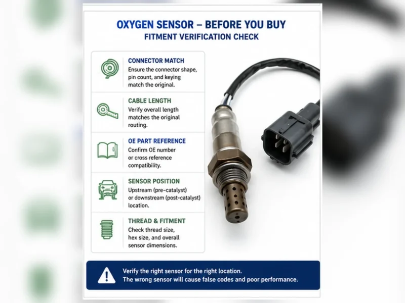
If the evidence supports replacement, the DTC still does not identify the sellable part. Complete a separate fitment check using OE reference, vehicle and engine, market or emissions configuration, exact bank and position, technology, connector, pin assignment, lead length and routing clips. This separation between diagnosis and fitment prevents a correct repair decision from becoming a wrong-position order.
Prepare una solicitud de ajuste o abastecimiento
Envíe el número OE, año/marca/modelo, detalles del motor o VIN, mercado y paquete de emisiones, posición exacta del banco/sensor, fotos del conector y de la pieza antigua, cantidad y cualquier requisito de embalaje o aprobación. Sunhyings revisará los datos proporcionados para determinar la capacidad y viabilidad de abastecimiento; el ajuste no se confirma hasta que se coteje la evidencia de aplicación.
Preguntas frecuentes
¿P0135 siempre significa que el calentador del sensor de oxígeno está defectuoso?
No. El elemento calefactor, fusible, cableado, conector, alimentación, tierra o circuito de control pueden ser los responsables.
¿Significa P0133 que el sensor debe ser reemplazado?
No. Primero confirme las condiciones de operación, la integridad del escape, el control de la mezcla y la prueba de respuesta especificada.
¿Es P0420 un código de sensor de O2?
Es un código de eficiencia del sistema catalizador que utiliza datos del sensor de oxígeno; no demuestra que un sensor de oxígeno haya fallado.
¿Puedo borrar el código para probar la reparación?
Registre primero los datos de diagnóstico. Siga el procedimiento del vehículo, ya que borrar códigos puede eliminar evidencia y restablecer los monitores de preparación.
¿Qué significa Banco 1 Sensor 2?
Comúnmente se refiere al sensor post-catalizador en el banco que contiene el cilindro 1, sujeto a confirmación específica del vehículo.