
When you compare lap joint flange vs slip on flange, you see practical differences in how the joint is built, how it is welded, and how it behaves during maintenance. Your choice affects bolt-up time, inspection access, corrosion strategy (mixed materials), and how much cyclic loading the joint can tolerate. In the field, lap joint flanges are often chosen for alignment and frequent dismantling because the backing ring swivels on the pipe end, while slip-on flanges are selected for quick fabrication and repeatable fit-up on low-to-moderate duty lines. For reference, flange dimensions and pressure-temperature classes are standardized within the ASME B16 series (selection still has to respect service severity, vibration, and maintenance plan). See the ASME B16 flange family overview here.
Use the quick table below as an initial screen, then confirm the decision using the “Pressure and Fatigue Performance” and “When to Use” sections (that is where most selection mistakes happen).
| Feature/Application | Lap Joint Flange | Slip-On Flange |
|---|---|---|
| Structural Feature | Moves freely on the pipe end (backs up a stub end) | Fixed after welding (double fillet welds) |
| Disassembly | Easy to disassemble/reassemble for cleaning or inspection | Not intended for frequent dismantling |
| Production Cost | Typically higher due to stub end + backing ring | Lower fabrication cost and common stock |
| Suitable Pressure | Often used on low-to-moderate severity lines; confirm class + service | Common in low-to-moderate severity lines; avoid severe cyclic/vibration |
| Common Applications | Corrosion-resistant systems, lined pipe, frequent maintenance | Utilities, general process lines where speed/cost matter |
| Sealing Performance | Depends heavily on stub end face, gasket, bolt-up practice | Depends on flange face finish + welding quality + bolt-up practice |
Choosing the right flange matters. Reliability is rarely lost because “the flange type is wrong” on paper—it is lost because the selected flange type does not match the actual duty: vibration, thermal cycling, gasket access, or the need to reuse parts. Sunhy supplies stainless steel flanges and matching components so you can keep the joint design consistent from purchasing to installation.
What Is a Lap Joint Flange?
Lap Joint Flange Design
You will find that a lap joint flange is not a “single piece flange.” It is a joint concept: a stub end is butt-welded to the pipe, and a loose backing flange (ring) transmits bolting load to the gasket through the stub end lap. The backing ring is not welded to the pipe, so it can rotate for bolt hole alignment. Many engineering references describe lap joint flanges as dimensionally similar to other flanges but used together with a lap joint stub end, and typically supplied without a raised face on the backing ring. See a standard description of lap joint flange construction and behavior here.
Tip: The rotatable backing flange simplifies alignment, but the seal quality still depends on the stub end face, gasket selection, and bolt-up practice.
Here is a quick overview of the typical lap joint flange structure:
| Component | Description |
|---|---|
| Backing Ring / Flat Ring | Loose ring with bolt holes; can be carbon steel or stainless; not in contact with process fluid in most designs. |
| Stub End | Butt-weld fitting that provides the sealing lap; material is typically matched to the pipe/process fluid. |
| Pressure Class & Facing Strategy | Defined by project piping class; verify face finish, gasket style, and bolt/stud grade in the line spec. |
| Material Pairing | Common pairing is corrosion-resistant stub end + economical backing ring, reducing alloy tonnage. |
Engineering selection note: when lap joint flange assemblies leak “mysteriously,” the root cause is often not the backing ring. Typical causes are (1) stub end lap not flat/parallel, (2) surface finish not compatible with gasket type, (3) uneven bolt load from poor tightening sequence, or (4) piping misalignment causing bending at the joint.
Material strategy you can actually use: In chloride-bearing water service, many owners keep the wetted parts in 316/316L and let the backing ring be carbon steel with coating, because the ring is outside the wetted envelope. In aggressive chemical service, the stub end alloy selection is driven by corrosion compatibility, while the backing ring is driven by mechanical strength and bolt-up stability. When you need the stub end itself, Sunhy’s stub end category page makes purchasing alignment easier: Stub Ends (Butt Weld Fittings).
How Lap Joint Flanges Work
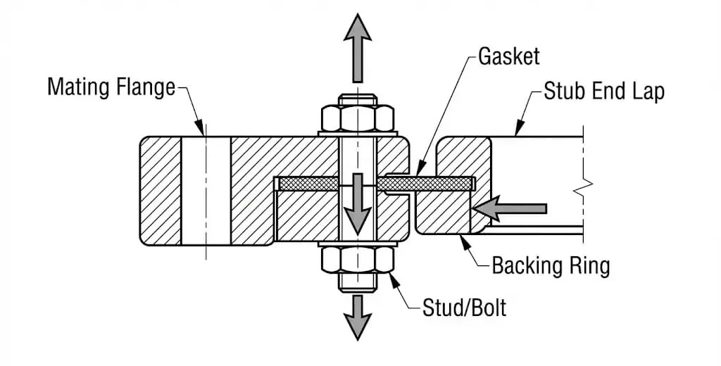
You achieve a seal with a lap joint flange by compressing the gasket between the mating flange face and the stub end lap. The backing ring’s role is to deliver bolt load; it is not the sealing surface. Because the backing ring is loose, you can align bolt holes after fit-up—this is the primary reason lap joint flanges survive in plants with tight clearances and frequent tear-down.
- Easy assembly and disassembly for cleaning, inspection, or spool replacement (without cutting the backing ring).
- Material flexibility: expensive alloy is concentrated in the stub end (wetted) instead of the entire flange.
- Alignment tolerance: the backing ring swivels to match bolt patterns during installation.
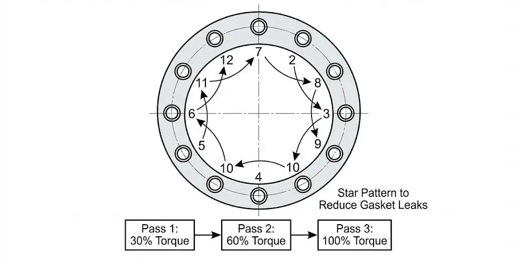
Installation steps that prevent repeat leaks (field checklist): (1) verify stub end lap face is clean and free of radial gouges, (2) confirm gasket type matches face and media, (3) check that the backing ring sits flat and does not “rock,” (4) tighten in a cross/star pattern in multiple passes, and (5) re-check bolt load after initial thermal stabilization if the site procedure allows it. Many gasket manufacturers publish tightening sequence and multi-pass practice because uneven bolt load is a leading cause of seepage. Example: Garlock bolting-up instructions (sequence and multi-pass guidance).
Common failure modes (what you troubleshoot on site):
- Weeping after start-up: usually uneven bolt load, gasket damage from debris, or misalignment bending the joint.
- Chronic re-torque requirement: gasket creep/relaxation (especially at temperature), poor surface finish, or bolt grade mismatch.
- Seal “looks fine” but leaks under vibration: lap joint assemblies can have lower fatigue tolerance than butt-welded hubbed joints; consider upgrading joint design where vibration is unavoidable.
Common Uses for Lap Joint Flanges
You will often see lap joint flanges where corrosion resistance and frequent disassembly are important: chemical processing, lined pipe systems, water treatment skids, and hygienic services that demand routine tear-down. They are also common on large diameters where bolt alignment effort becomes a schedule risk. Engineering references commonly describe lap joint flange assemblies as advantageous for swivel alignment and for reusing backing rings when the wetted stub end is replaced. See typical lap joint flange advantages and limitations here.
| Application Area | Benefit of Lap Joint Flanges |
|---|---|
| Chemical Processing | Material pairing (alloy stub end + economical ring), easier maintenance access |
| Water Treatment | Quick disassembly for cleaning, easier bolt alignment on packaged skids |
| Food Industry | Frequent tear-down and cleaning (when designed with hygienic considerations) |
Where you should be cautious: if your line sees strong vibration, frequent thermal cycling, or bending loads from poor supports, the joint selection should be reviewed by the piping engineer. A lap joint assembly can be the right answer for maintenance, but it is not a “free upgrade” in fatigue performance.
What Is a Slip-On Flange?
A slip-on flange gives you a straightforward, cost-focused way to connect pipes in many systems. You slide the flange over the pipe and weld it in place. This approach reduces fit-up difficulty because the pipe can be positioned inside the flange bore before welding. In practice, slip-on flanges show up heavily in utilities and general process lines where the line is not designed for frequent dismantling.
Slip-On Flange Structure
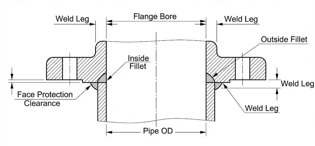
You will notice that a slip-on flange is a single piece with a central bore slightly larger than the pipe OD. The connection is typically made with two fillet welds (inside and outside). Many engineering references note that the strength under internal pressure and fatigue life are lower than hubbed butt-weld designs, and they call out practical fit-up clearance so the flange face is not damaged during welding. See slip-on flange weld details and fit-up notes here.
Note: Slip-on flanges are forgiving on fit-up, but once welded they are fixed. Alignment and weld quality determine long-term leakage risk more than “flange type” alone.
Here is a quick comparison of slip-on flange structure with weld neck flanges:
| Feature | Slip-on Flange | Weld Neck Flange |
|---|---|---|
| Connection Method | Slides over pipe, double fillet weld | Butt weld to tapered hub |
| Installation | Simple, quick, less precision fit-up | More fit-up control; weld is inspectable |
| Pressure/Cyclic Severity | Typically selected for lower severity duty | Preferred for higher cyclic/vibration duty |
| Strength & Stress Distribution | Moderate; fillet weld behavior matters | Superior stress distribution through hub |
Standard slip on flange dimensions follow industry standards such as ANSI/ASME dimensional practice (selection guidance), EN1092, and DIN. Sizes range widely, but your project piping class controls what is actually acceptable (pressure class, facing type, gasket, bolting, and NDE requirements).
Welding quality control you should not skip: tack the flange in place, verify squareness, weld sequence to minimize distortion, and confirm there is no undercut or lack of fusion at the fillet toes. If you operate at temperature cycles, weld toe cracking is a known failure mode on fillet-welded attachments—your inspection plan should reflect that risk.
How Slip-On Flanges Work
You achieve a joint by sliding the slip-on flange over the pipe and welding it on both sides. The gasket seals between flange faces; the welds provide attachment and load transfer. This design can be reliable in appropriate duty. The typical leak drivers are not exotic: poor face cleanliness, wrong gasket, uneven bolt load, and welding distortion that creates non-parallel faces.
Practical sealing controls (what prevents nuisance leaks): (1) confirm flange faces are parallel after welding, (2) use gasket material compatible with temperature/media, (3) tighten bolts in a cross pattern in multiple passes, and (4) document final torque/turn-of-nut method per site procedure. If your plant follows an industry practice for bolted joints, align the installation method accordingly (many sites reference ASME PCC-1 concepts for assembly discipline). ASME PCC-1 training overview (assembly discipline).
Typical Applications for Slip-On Flanges
You will find slip-on flanges in many industries where pressure is moderate and frequent disassembly is not required: utilities, water distribution, HVAC/process support, and non-critical refinery services. The biggest selection mistake is using slip-on flanges on lines that behave like “dynamic equipment piping” (pumps, compressors, strong vibration, frequent thermal cycling) without checking cyclic severity.
- Oil and gas utility lines for transporting fluids at lower severity duty
- Petrochemical plants for non-severe service headers
- Water treatment facilities for distribution and filtration skids
- Wastewater systems where quick fabrication and cost control dominate
Slip-on flanges offer a practical solution for general industrial piping. Their value is speed and cost; their limitation is cyclic/vibration tolerance compared to hubbed butt-weld joints.
Lap Joint Flange vs Slip On Flange: Key Differences
When you compare lap joint flange vs slip on flange, focus on the things that drive failures: weld type (butt vs fillet), gasket access, alignment tolerance, and how the joint behaves when the line expands, contracts, or vibrates. The “best” flange is the one that matches the actual operating pattern and the maintenance plan.
Design and Components
Lap joint flanges and slip-on flanges differ in structure and load path. A lap joint flange assembly uses a stub end welded to the pipe and a loose backing ring that rotates; the seal is created at the stub end lap. A slip-on flange is welded to the pipe and becomes part of the pressure boundary attachment. Engineering references commonly summarize the strength/fatigue penalty of fillet-welded attachments compared with butt-welded hubbed joints, and they describe lap joint assemblies as typically similar in pressure-holding ability to slip-on assemblies, with fatigue performance dependent on the whole assembly (stub end + ring + bolt load). Reference description and comparative notes.
Comparison table (design and components):
| Feature | Lap Joint Flange | Slip-On Flange |
|---|---|---|
| Design | Stub end + backing ring | Single-piece flange |
| Welding | Stub end butt-welded; ring not welded | Inside + outside fillet welds |
| Movement | Ring swivels for bolt-up | Fixed after welding |
| Flexibility | High for alignment and tear-down | Low after welding |
| Material Pairing | Possible to mix materials (wetted vs non-wetted) | Often same as pipe for consistency |
| Best Fit | Frequent maintenance, lined systems, alignment constraints | General service, cost-optimized fabrication |
Tip: If your shutdown plan includes routine gasket replacement or spool swaps, lap joint assemblies reduce rework time because the ring can be reused and alignment is easier.
Installation and Alignment
Installation drives real cost. Lap joint flanges simplify alignment because the ring swivels on the stub end. That matters on large-bore spools, tight rack spaces, or when the mating flange bolt pattern is fixed. For maintenance, the ring can often be reused while the stub end (wetted) is replaced.
Slip-on flanges are fast to fabricate: slide on, set dimension, tack, weld. The risk is that welding distortion or poor squareness creates non-parallel faces and uneven gasket compression. Once welded, alignment correction is rework.
Note: If you expect frequent disassembly, the lap joint ring saves time. If your system is “install once, run for years,” the slip-on flange can be the more economical choice—provided the duty is not severe cyclic.
Pressure and Fatigue Performance
Pressure class is defined by the applicable standard and project piping class, but service severity is where selection errors occur. Fillet-welded attachments are generally less tolerant of vibration and thermal cycling than butt-welded hubbed joints, and many engineering references quantify this as reduced strength and fatigue life for slip-on designs relative to weld neck designs. The same references describe lap joint assemblies as not materially better in pressure-holding ability than slip-on assemblies, with fatigue life dependent on the whole assembly and often treated as lower than hubbed butt-weld joints. See comparative notes on slip-on and lap joint fatigue/strength.
The table below avoids “fake precision” and shows what you can actually use during selection review.
| Criterion | Lap Joint Flange Assembly | Slip-On Flange |
|---|---|---|
| Typical severity fit | Low-to-moderate duty, frequent maintenance, alignment constraints | Low-to-moderate duty, cost-optimized fabrication |
| Cyclic/vibration tolerance | Often treated as limited vs hubbed butt-weld joints; review for dynamic lines | Often treated as limited vs hubbed butt-weld joints; review for dynamic lines |
| Key performance driver | Stub end face + bolt load uniformity | Weld quality + face parallelism + bolt load uniformity |
| Upgrade trigger | Chronic leaks after thermal cycles or vibration events | Weld toe cracking, repeated re-torque, or vibration-driven seepage |
Sunhy’s stainless steel flange selection guide helps you map flange type to service severity and maintenance plan, not just “pressure rating on paper.”
Cost and Maintenance
Cost is not only purchase price. You should compare total cost of ownership: fabrication hours, inspection access, shutdown time, and whether parts can be reused.
Lap joint assemblies: higher material count (stub end + ring), but maintenance can be faster because the ring is reusable and alignment is easy. In corrosive or erosive services, replacing only the wetted stub end can be a practical strategy.
Slip-on flanges: lower initial cost and fast welding, but repeated dismantling is not the design intent. If a slip-on flange needs replacement, the usual path is cutting, re-fit, and re-welding—time and quality risk during shutdown.
Summary of typical maintenance tasks:
| Maintenance Task | Slip-On Flanges | Lap Joint Flanges |
|---|---|---|
| Periodic Inspection | Check bolts, weld toes, corrosion, face condition | Check bolts, stub end lap face, ring wear, face condition |
| Cleaning | Clean faces and gasket seating area | Clean stub end lap and mating face |
| Corrosion Control | Coatings/material selection; inspect weld heat-affected zone | Protect backing ring if carbon steel; inspect stub end (wetted) |
| Leak Response | Verify torque pattern, gasket condition, face parallelism | Verify torque pattern, stub end lap integrity, gasket condition |
| Documentation | Maintain torque/inspection records | Maintain torque/inspection records |
Good flange performance is usually “boring”: clean faces, correct gasket, correct bolting, and a disciplined tightening method. Poor bolt-up practice can make either flange type leak.
Quick Reference Table
For a concise overview, use the table below to compare lap joint flange vs slip on flange at a glance:
| Feature/Application | Lap Joint Flange | Slip-On Flange |
|---|---|---|
| Structural Feature | Moves freely on the pipe end | Connected by two fillet welds |
| Disassembly | Easy to disassemble and assemble | Easy to process and install |
| Production Cost | Higher than slip-on flanges (stub end required) | Lower production cost |
| Suitable Pressure | Often used where alignment/maintenance dominate; confirm service severity | Common in low-to-moderate duty; avoid severe cyclic service |
| Common Applications | Corrosion-resistant connections, frequent disassembly | General medium/low duty connections |
| Sealing Performance | Highly dependent on stub end + bolt-up discipline | Highly dependent on welding + bolt-up discipline |
You can use this table to shortlist your choice, then confirm using the scenario checklist below.
Pros and Cons of Lap Joint and Slip-On Flanges
Lap Joint Flange Advantages and Disadvantages
You want to know the strengths and weaknesses of lap joint flanges before making a decision. The biggest advantages are alignment and maintainability; the biggest risks are applying them in dynamic service without reviewing fatigue/vibration and ignoring stub end face quality. Engineering references also describe lap joint assemblies as typically used in low-pressure/non-critical applications and as advantageous for mixing materials and reusing backing rings. Reference summary of lap joint advantages/limits.
| Advantages | Disadvantages |
|---|---|
| Fast bolt alignment (swivel ring) | Not a default choice for high vibration/cyclic service |
| Frequent dismantling is practical | Seal depends on stub end face and bolt-up discipline |
| Material pairing reduces alloy tonnage | Two-part assembly increases purchasing complexity |
| Backing ring can be reusable | Misalignment bending can cause nuisance leaks |
| Works well with lined/erosive services | Wrong stub end spec can erase the advantages |
Engineering caution that shows up in audits: lap joint rings are sometimes purchased correctly, but the stub end is purchased “as a commodity.” Stub end face, lap thickness, and standard compliance matter as much as the ring. Treat the stub end as the sealing component, not a generic butt-weld fitting.
Slip-On Flange Advantages and Disadvantages
You should consider slip-on flanges if you need a cost-effective and fast-to-fabricate option for lower severity duty. They are common, easy to fit, and widely stocked. The limitations show up under vibration and thermal cycling because the attachment relies on fillet welds and face distortion control.
The table below compares slip-on flange features with weld-neck flanges:
| Aspect | Slip-On Flange | Weld-Neck Flange |
|---|---|---|
| Strength | Lower; selection should consider cyclic/vibration duty | High; preferred for severe duty |
| Sealing | Can be reliable if faces remain parallel and bolt load is uniform | Excellent for severe duty when properly assembled |
| Ease of Installation | Simple and cost-effective | More demanding fit-up and welding |
| Stress Resistance | Limited under dynamic loads | Superior for vibration/thermal cycling |
| Cost | Lower initial fabrication cost | Higher due to hubbed design and welding |
Advantages of Slip-On Flanges:
- Fast fit-up and fabrication
- Lower cost for budget-sensitive projects
- Wide availability across sizes and materials
Disadvantages of Slip-On Flanges:
- Less suitable for severe cyclic/vibration duty
- Quality depends strongly on welding and distortion control
Tip: Select slip-on flanges for low-to-moderate duty lines where cost and fabrication speed matter, and where the joint is not planned for frequent dismantling.
When to Use Lap Joint Flanges or Slip-On Flanges
Best Scenarios for Lap Joint Flanges
You should choose lap joint flanges when your pipeline needs frequent maintenance, easy alignment, or a mixed-material corrosion strategy (alloy stub end + economical backing ring). They are common in chemical processing, lined systems, water treatment skids, and services where tear-down is planned.
Common scenarios for lap joint flanges:
- Chemical plants needing corrosion-resistant wetted materials with cost control
- Lined pipe systems where a loose backing ring simplifies installation
- Water treatment skids requiring periodic dismantling and cleaning
- Food and beverage lines that are routinely opened (with hygienic design controls)
- Systems with frequent gasket changes where re-alignment time is costly
Tip: If your maintenance strategy includes reusing non-wetted components, lap joint assemblies can reduce spare parts cost—provided the stub end is specified correctly.
Engineering example (field-proven pattern): A plant runs a chloride-bearing utility line where the pipe spec is 316L for corrosion compatibility. The joint is built with a 316L stub end (wetted) and a coated carbon steel backing ring. During planned cleaning shutdowns, the spool is dismantled quickly without fighting bolt alignment, and the backing ring is reused when the wetted stub end is replaced due to wear.
Best Scenarios for Slip-On Flanges
You should use slip-on flanges for installations where cost and fabrication speed dominate, and where the service is not severe cyclic or high vibration. They work well on utility headers and general process lines. If the line is tied to rotating equipment or sees frequent thermal cycling, review the joint choice carefully.
Ideal uses for slip-on flanges:
- Residential and commercial HVAC/process support systems
- Water distribution pipelines
- General service headers in plants (non-severe duty)
- Low-to-moderate duty lines where fabrication speed matters
- Installations where dismantling is rare
Note: Slip-on flanges can be reliable when welding and distortion are controlled. For corrosive environments, match material and consider surface protection practices aligned with your site standards.
Practical Examples
You can see the impact of selecting the wrong flange type in predictable failure patterns:
Example 1 — dynamic line cracking: a slip-on flange is installed on a line that experiences vibration and thermal cycling (near a pump discharge or compressor run). The weld toe becomes a stress raiser; small cracks propagate and the joint starts to weep. The corrective action is usually not “re-torque harder.” It is reassessing joint type, improving support to reduce vibration, and upgrading to a joint design better suited for cyclic duty.
Example 2 — maintenance-driven downtime: a skid package is built with slip-on flanges on a line that is dismantled frequently for cleaning. Each shutdown turns into rework because bolt alignment is slow and gasket seating surfaces get damaged during repeated separation. A lap joint assembly with properly specified stub ends often reduces bolt-up time and preserves reusable components.
Example 3 — corrosion strategy mismatch: an alloy line is built with full alloy slip-on flanges, even though only the wetted surfaces require alloy. The system performs, but purchasing cost is higher than necessary. A lap joint strategy can reduce alloy tonnage when the backing ring stays out of wetted contact.
| Case Pattern | Typical Cause | Corrective Direction |
|---|---|---|
| Weeping after thermal cycles | Uneven bolt load, face distortion, gasket relaxation | Improve bolt-up discipline; confirm gasket/face match; review joint type |
| Cracking at weld toe | Dynamic loads on fillet-welded attachment | Review supports; consider hubbed butt-weld joint for cyclic duty |
| High downtime during cleaning | Frequent dismantling not matched to joint type | Consider lap joint assembly for alignment and reuse |
Sunhy offers custom flange solutions and engineering support for your industry needs. You can use Sunhy’s product pages to keep stub ends, flanges, and material grades aligned to one piping class (this prevents mixed procurement that later causes fit-up problems).
You now understand the key differences between lap joint and slip-on flanges. Lap joint assemblies emphasize alignment and maintainability; slip-on flanges emphasize fabrication speed and cost control. Your final choice should reflect service severity (vibration/thermal cycling), inspection plan, and how often the joint is opened.
| Why Choose Sunhy? | Description |
|---|---|
| Quality Control | Consistent machining/forging controls help keep faces flat, bolt holes accurate, and fit-up repeatable. |
| Standards Alignment | Supply can be aligned to project requirements (ASME/EN/DIN), with traceability and documentation as required. |
- Request a quote for your next project.
- Reach out for guidance on selecting flange type + stub end configuration for your maintenance plan.
- Explore Sunhy’s flange selection guide to map flange type to duty and inspection.
FAQ
What is the main difference between lap joint and slip-on flanges?
You will notice the main difference in their load path and attachment. Lap joint assemblies use a stub end (butt weld) plus a loose backing ring that rotates for bolt alignment. Slip-on flanges are welded to the pipe with fillet welds and become fixed after welding.
When should you choose a lap joint flange?
You should choose a lap joint assembly when your system needs frequent disassembly, easy alignment, or mixed materials for corrosion strategy. It is common in chemical, lined systems, water treatment skids, and services with planned tear-down.
Are slip-on flanges suitable for high-pressure applications?
Do not treat slip-on flanges as a default choice for severe duty. Even when pressure class is defined by the piping specification, slip-on flanges are commonly avoided on lines with high vibration, frequent thermal cycling, or severe cyclic loading. For those services, hubbed butt-weld designs are typically preferred.
Can you use different materials for the stub end and backing flange in lap joint flanges?
Yes. That is one of the main engineering reasons to use lap joint assemblies. The stub end (wetted) can match corrosion requirements, while the backing ring can be a more economical grade if it does not contact the process fluid.
How do Sunhy stainless steel flanges ensure quality and reliability?
Sunhy focuses on controlled manufacturing and inspection so flange faces, bolt patterns, and fit-up remain repeatable. Reliable sealing depends on flatness, surface condition, correct gasket selection, and disciplined bolt-up procedures—Sunhy’s product consistency supports those controls.
What bolt tightening practice helps prevent leaks for both flange types?
Use a cross/star pattern in multiple passes, keep faces clean, and avoid “one-shot” tightening. Many gasket manufacturers publish bolting-up instructions with sequence and staged tightening guidance. Always follow your site procedure and torque method (or PCC-1 style discipline where applicable).
What is the most common cause of repeat leakage on lap joint assemblies?
The most common causes are stub end lap face damage/poor finish, debris trapped at the gasket seating area, and uneven bolt load from poor tightening sequence. The backing ring usually is not the root cause—the stub end is the sealing component.


