")
A flange is a mechanical part that connects pipes, valves, pumps, and other equipment, ensuring a secure and leak-free joint in piping systems. In practice, a flange joint is not “just bolting two parts together” — the sealing performance depends on facing type, gasket selection, bolt load (preload), alignment, and how the joint behaves under temperature swings and vibration. The main question you might ask is, what are the different types of flanges used in piping? You find several types of flanges, each designed for specific needs. Choosing the right flange type is crucial for safety, reliability, and long-term performance. The global pipe flange market shows its importance:
- The global market size for pipe flanges reached USD 4,876.8 million in 2023.
- Experts expect the market to grow to about USD 8,655.6 million by 2033, with strong demand from industries like oil and gas, power, and chemicals.
Engineering note: Market reports use different scope and methodology, so treat those values as “industry scale indicators,” not a design basis. Your design basis should always come from the applicable code, piping class, and the actual operating envelope (pressure/temperature/medium/cycles).
You will most often encounter these types of flanges in industrial piping:
- Blind flange
- Weld neck flange
- Slip on flange
- Socket weld flange
- Threaded flange
- Lap joint flange
- Long weldneck flange
Understanding the types of flanges helps you make informed choices for your projects. If your project specification says “ANSI flange,” note that in many plants this is shorthand for ASME B16.5 / B16.47 dimensional systems (ANSI historically accredited standards; the commonly used dimensional standards are published under ASME).
What Are Flanges in Piping?
Flange Definition
A flange is a mechanical device that connects pipes, valves, pumps, and other equipment in a piping system.
You use flanges to create strong, leak-proof joints that can be assembled or taken apart easily. Flanges come in many shapes and sizes, but all serve the same basic purpose: to join two parts together securely. In maintenance-heavy units (filters, strainers, heat exchangers, instrument tie-ins), the ability to open a joint without cutting pipe is often the primary reason flanges exist.
Tip: Flanges must follow strict standards to ensure safety and compatibility in piping systems. If two flanges are “same NPS” but from different standards (ASME vs EN vs JIS), the bolt circle, thickness, and facing details may not match.
You find that organizations like ASME (American Society of Mechanical Engineers) set the rules for flange design and use. These standards help you choose the right flange for your project and make sure everything fits together. For ASME dimensional systems, the official references include ASME B16.5 (common sizes) and ASME B16.47 (large diameter), and your system design is typically governed by piping codes such as ASME B31.3 (process) or ASME B31.1 (power) depending on service.
- Flanges are defined by standards such as ASME B16.5 and ASME B16.47, which specify dimensions and pressure classes.
- ASME B16.5 covers nominal pipe sizes from 1/2″ to 24″ and includes pressure classes like 150, 300, 400, and more.
- ASME standards ensure compatibility and safety in piping systems by detailing design and manufacturing specifications.
- Standardization is crucial for ensuring that flanges fit together correctly and can withstand the required pressures and temperatures.
- ASME standards are recognized for their specifications related to pressure applications, promoting safety and reliability.
Field example #1 (selection mismatch → rework): A maintenance team replaced a corroded flange with “same NPS, same class” but from a different standard family. Bolt holes did not line up, forcing hot rework and unplanned downtime. Prevent this by confirming: standard system (ASME/EN/JIS), pressure class/PN, facing type, bolt circle, and thickness before ordering.
Role in Piping Systems
Flanges play several key roles in piping systems.
You rely on flanges for much more than just connecting pipes. Here are the main functions:
- Pipeline Connection: Flanges connect pipes and components securely and leak-proof.
- Pressure Containment: They contain pressure within a system, ensuring safe operation.
- Sealing: Flanges create a tight seal to prevent leaks.
- Alignment and Support: They ensure proper alignment and provide structural support.
- Branch Connections: Flanges allow for additional connections without interrupting flow.
- Flow Control: Used for flow measurement and control.
- Vibration Dampening: They help reduce vibrations in piping systems (when supported correctly).
- Corrosion Resistance: Material choice impacts corrosion resistance.
- Accessibility for Inspection and Maintenance: Flanges facilitate easy access for maintenance.
- Pressure Relief: They can integrate safety relief valves to protect the system.
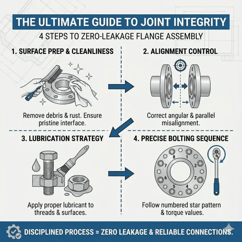
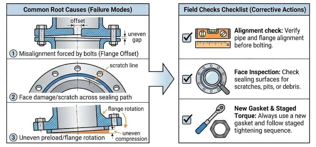
Practical checklist (what actually makes a flange joint reliable):
- Facing + gasket compatibility: RF/FF/RTJ must match gasket type and seating stress.
- Bolt preload: correct bolting sequence and torque steps; avoid uneven compression and flange rotation.
- Alignment: avoid forcing bolt-up; misalignment translates into bending load and leaks.
- Surface condition: scratches across the sealing path, corrosion pits, or embedded debris can defeat even “new gasket + high torque.”
You see that flanges are essential for building safe, reliable, and easy-to-maintain piping networks. By understanding their definition and role, you can make better decisions when designing or maintaining a piping system.
Main Types of Flanges
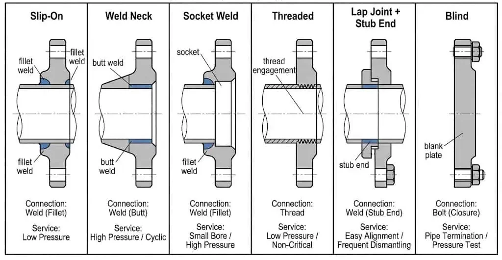
Slip-On Flange
Slip-on flanges are designed for easy installation and are ideal for low-pressure, low-temperature piping systems.
You use slip-on flanges by sliding them over the pipe and welding them in place. This design makes them simple to align and install, which saves time and effort. Their large inner diameter allows you to insert the pipe easily. You often find slip-on flanges in water treatment plants, chemical production facilities, and pipelines for petroleum and natural gas.
Key characteristics and typical applications:
- Easy to install and align (especially in tight rack piping)
- Suitable for low-pressure, low-temperature environments
- Common in water treatment, chemical processing, and oil and gas utilities
Advantages:
- Quick and cost-effective installation
- Versatile for many types of flanges applications
- Affordable compared to other flange types
Disadvantages:
- Lower strength than other flange types (stress transfer is not as efficient as weld neck)
- Not suitable for high-pressure systems or severe cyclic service
| Aspect | Slip-On Flange | Weld Neck Flange |
|---|---|---|
| Strength | Lower, for low-pressure systems | High, for demanding environments |
| Sealing | Moderate | Excellent |
| Ease of Installation | Simple, quick | Complex, needs skilled labor |
Field example #2 (recurring seepage at slip-on): On a cooling water header, a slip-on flange leaked after a pump upgrade introduced vibration. Root cause was flange rotation from uneven bolt-up plus misalignment that was “pulled in” by bolts. Fix: correct alignment (no forced bolt-up), new gasket, staged tightening, and adding proper pipe supports near the pump nozzle.
Weld Neck Flange
Weld neck flanges provide superior strength and are best for high-pressure and high-temperature applications.
You recognize weld neck flanges by their long, tapered hub. This feature helps distribute stress evenly, reducing the risk of failure. You must use butt-welding to attach them, which creates a strong, leak-proof joint. Weld neck flanges are common in industries like oil and gas, power generation, chemical processing, and marine systems. They are also the go-to choice when you expect thermal cycling, higher bending loads, or fatigue-sensitive service.
| Key Features of Weld Neck Flanges | Advantages of Weld Neck Flanges |
|---|---|
| Long, tapered hub | Superior strength and durability |
| Requires butt-welding | High resistance to stress |
| Ideal for high-pressure systems | Leak-proof connection |
| Reduces turbulence | Reliable in extreme conditions |
Typical applications:
- Oil and gas pipelines and refineries
- Power plants (steam, gas, nuclear)
- Chemical and pharmaceutical manufacturing
- Marine and mining industries
Engineering note: In fatigue-prone areas (pump discharge, compressor lines, hot cycling), weld neck is often chosen not because the gasket seals better, but because the joint geometry reduces stress concentration at the pipe-to-flange transition.
Socket Weld Flange
Socket weld flanges are best for small-diameter, high-pressure piping where strong, leak-free joints are needed.
You install socket weld flanges by inserting the pipe into the flange socket and then welding around the pipe. This method creates a smooth internal surface, which reduces flow disturbances. You often use socket weld flanges in instrumentation lines, process sampling systems, and high-pressure service lines.
| Application Type | Key Features |
|---|---|
| Instrumentation Lines | Secure, vibration-resistant, easy maintenance |
| Process Sampling | Leak-free, clean internal surfaces, high-strength |
| Small Bore Piping | Strong joints, cost-effective for complex networks |
| High-Pressure Service | Reliable for critical applications, suitable for hydraulic systems |
| Steam Systems | Resistant to thermal cycling, robust for condensate return |
Comparison with slip-on flanges:
- Socket weld flanges take longer to install and cost more initially, but they offer better performance in high-pressure systems.
- They require professional welders but provide lower long-term maintenance costs.
Typical engineering practice (range, depends on spec): many shops leave a small axial gap between pipe end and socket shoulder (often around 1–2 mm / ~1/16 in) to reduce restraint and cracking risk during thermal expansion. Verify the requirement in your project spec and applicable code.
Blind Flange
Blind flanges seal the end of a piping system or isolate a section for maintenance or inspection.
You use blind flanges when you need to stop the flow in a pipeline or close off a vessel opening. They do not have a center hole, so they block the passage completely. Blind flanges are essential for safe maintenance and prevent contamination during repairs. In commissioning and hydrotest, blind flanges also act as temporary boundaries — which means the bolt load and gasket selection must be treated as “real service,” not a placeholder.
Main functions:
- Seal the ends of pipelines
- Isolate sections for maintenance
- Prevent contamination
Pressure ratings (ASME B16.5): The values below are commonly referenced as typical class ratings at 100°F (38°C) for common material groups; actual allowable pressure depends on material group and temperature — always verify against the official pressure–temperature tables for the selected material.
| Flange Class | Max Pressure (at 100°F) |
|---|---|
| 150 | 285 psi |
| 300 | 740 psi |
| 400 | 990 psi |
| 600 | 1,480 psi |
| 900 | 2,220 psi |
| 1500 | 3,705 psi |
| 2500 | 6,175 psi |
")
Field example #3 (blind flange blow-by during hydrotest): A test blind leaked at 1.1× test pressure. Root cause was reused gasket plus uneven bolt tightening (one side bottomed early). Corrective action: new gasket, staged torque in a cross pattern, and re-check bolt relaxation after initial pressurization (only if gasket type and procedure allow).
Lap Joint Flange
Lap joint flanges offer flexibility and are ideal for systems that require frequent assembly and disassembly.
You use lap joint flanges with a stub end, which allows the flange to rotate around the pipe. This design makes alignment easy and reduces installation time. Lap joint flanges work well in low-pressure applications and where corrosion resistance is important — especially when the stub end is made from a corrosion-resistant alloy and the backing flange is a cheaper material.
| Unique Features | Preferred Scenarios |
|---|---|
| Easy assembly/disassembly | Low-pressure applications |
| Alignment flexibility | Maintenance-heavy industries |
| Cost-effective | Frequent disassembly requirements |
| Corrosion resistance | Use with exotic materials |
| Not for high temperatures | Not for high-pressure applications |
| Handles slight misalignment |
Threaded Flange
Threaded flanges connect to pipes without welding, making them perfect for quick assembly and disassembly in low-pressure systems.
You screw threaded flanges onto the pipe, which makes installation fast and reduces safety risks. This design is especially useful for small-diameter pipes and in places where welding is not possible or safe. Engineering limits usually come from vibration, cyclic loads, and the risk of thread leakage paths if sealant is mismatched to the medium.
- Threaded flanges enable connections without welding, which improves installation efficiency.
- You can easily screw them onto pipes, making assembly and disassembly quick.
- They are ideal for low-pressure systems and smaller pipes.
- The absence of welding reduces safety hazards during installation.
Tip: Threaded flanges are best for temporary connections or systems that need frequent maintenance. If vibration is present, plan supports and consider a connection type that cannot loosen over time.
Field example #4 (threaded leak after start-up): A small-bore threaded flange on instrument air weeped after compressor start. Root cause was vibration + insufficient thread engagement + unsuitable sealant. Fix: re-thread to correct tolerance/engagement, use sealant approved for the medium, add support, and consider switching to welded small-bore in high-vibration zones.
You now have a clear overview of the main types of flanges used in piping systems. Each of these flange types serves a specific purpose, and understanding their differences helps you choose the right one for your project. The right selection ensures safety, reliability, and long-term performance in your piping network.
Specialty Flange Types
Reducer Flange
A reducer flange lets you decrease the size of a pipeline by one or two sizes.
You use reducer flanges when you need to connect pipes of different diameters without using a separate reducer fitting. This design saves space and reduces the number of joints in your system. You often see reducer flanges in process plants where pipelines change size to control flow or pressure. Engineering check: consider local velocity increase and erosion risk when reducing bore, especially with two-phase or solids-laden service.
Expander Flange
An expander flange increases the bore of a pipeline by one or two sizes.
You use expander flanges to connect a smaller pipe to a larger one, especially when joining to pumps, compressors, or valves with bigger inlets. This flange type helps you avoid extra fittings and keeps the connection strong and leak-free. Engineering check: avoid sudden expansion right at sensitive equipment where flow separation can cause vibration; use reducers/expanders per hydraulic design where needed.
Long Weld Neck Flange
A long weld neck flange provides extra support for high-pressure and high-temperature applications.
You choose long weld neck flanges for critical service conditions. The extended neck helps handle thermal expansion and mechanical stress. You often find these flanges in refineries, power plants, and chemical processing facilities. They are also used where nozzle reinforcement or extended hub geometry is required by design.
Quick Comparison Table:
This table shows the main differences between reducer, expander, and long weld neck flanges.
| Flange Type | Function | Applications |
|---|---|---|
| Reducer Flange | Decreases the bore of a pipeline | Used when reducing the size of a pipeline by 1 or 2 sizes |
| Expander Flange | Increases the bore of a pipeline | Connects pipes to devices with different inlet sizes |
| Long Weld Neck Flange | Provides extra support in tough environments | Used in high-pressure, high-temperature, and critical applications |
Nipoflange and Weldoflange
Nipoflange and weldoflange create branch connections in piping systems.
You use nipoflanges and weldoflanges when you need to add a branch line to an existing pipeline. These flanges combine the features of a welding outlet and a flange, making installation easier and more reliable. Engineering note: branch connections must be checked for reinforcement, local stress, and inspection accessibility — not only “it fits.”
- Nipoflange: You find these in manufacturing, food processing, waterworks, heat exchangers, mining, nuclear power, plumbing, oil and gas, and fire protection systems.
- Weldoflange: You use these for branch connections where you need high integrity and reliability, especially in the piping industry.
Swivel Flange
A swivel flange allows for easy alignment of bolt holes during installation.
You use swivel flanges in pipelines, especially offshore and subsea systems. The rotating design helps you align the flange quickly, which saves time and effort during assembly. Engineering check: confirm sealing design (often paired with RTJ-style concepts), material compatibility, and assembly procedure for offshore constraints.
- Swivel flanges work best in offshore and subsea pipelines.
- You benefit from quick bolt alignment, which is important for large-diameter or heavy piping.
Tip: Specialty flanges help you solve unique piping challenges, making your system safer and easier to maintain.
Comparison of Flange Types
Design Differences
The main flange types differ in how they connect to pipes and handle pressure.
Each flange design has unique features that suit specific needs. For example, slip-on flanges slide over the pipe and require welding, making them easy to install for low-pressure systems. Threaded flanges use pipe threads, so you do not need to weld them, which works well for small pipes. Socket weld flanges need a single weld for a secure fit, while blind flanges have no opening and seal off the end of a pipe or valve.
| Flange Type | Design Characteristics | Typical Applications |
|---|---|---|
| Slip-on Flange | Slides over pipe end, welded in place, simple alignment | Low-pressure systems |
| Threaded Flange | Tapered threads, no welding needed, quick assembly | High-pressure gas/liquid systems |
| Socket Weld Flange | Pipe fits into socket, single fillet weld, smooth internal surface | Various piping systems |
| Blind Flange | Solid plate, no center hole, blocks flow | Sealing or isolating pipelines |
Application Differences
You select flange types based on pressure, environment, space, and cost.
Different projects need different flanges. Here are the main factors you should consider:
- Pressure levels: Some flanges handle higher pressures better.
- Environmental conditions: Corrosive chemicals or high heat may require special materials.
- Ease of assembly and disassembly: Choose flanges that make maintenance simple if you need frequent access.
- Physical space constraints: Tight spaces may limit your options.
- Cost considerations: Balance performance with your budget.
Tip: Always match the flange to your system’s needs for safety and efficiency. If the line is fatigue-sensitive, prioritize joint geometry and support over “easy installation.”
Quick Reference Table
You can compare flange types by looking at key parameters.
This table helps you quickly see the differences:
| Parameter | Slip-on | Threaded | Socket Weld | Blind |
|---|---|---|---|---|
| Flange design | Over pipe, welded | Tapered threads | Socket + weld | Solid plate |
| Pressure class | Low | High | Medium/High | All classes |
| Assembly | Easy | Very easy | Moderate | Easy |
| Maintenance | Simple | Very simple | Moderate | Simple |
| Typical use | Water, oil | Gas, small pipe | Process lines | Isolation |
Selection decision table (engineering-oriented):
| Condition | Prefer | Why |
|---|---|---|
| High pressure / thermal cycling / fatigue risk | Weld neck | Better stress distribution at pipe-to-flange transition |
| Low pressure utilities; fast field fit-up | Slip-on | Easy alignment; economical |
| Small-bore high pressure, controlled welding | Socket weld | Strong joint for small sizes; compact |
| Frequent disassembly + exotic alloy stub end | Lap joint | Lower cost backing flange; easy alignment |
| No hot work allowed / temporary tie-in | Threaded (with limitations) | No welding; quick assembly; watch vibration and leakage paths |
| Isolation / hydrotest boundary | Blind | Blocks flow; treat as full-strength pressure boundary |
You should always check size, thickness, bolt holes, standards, pressure class, and materials before making your final choice.
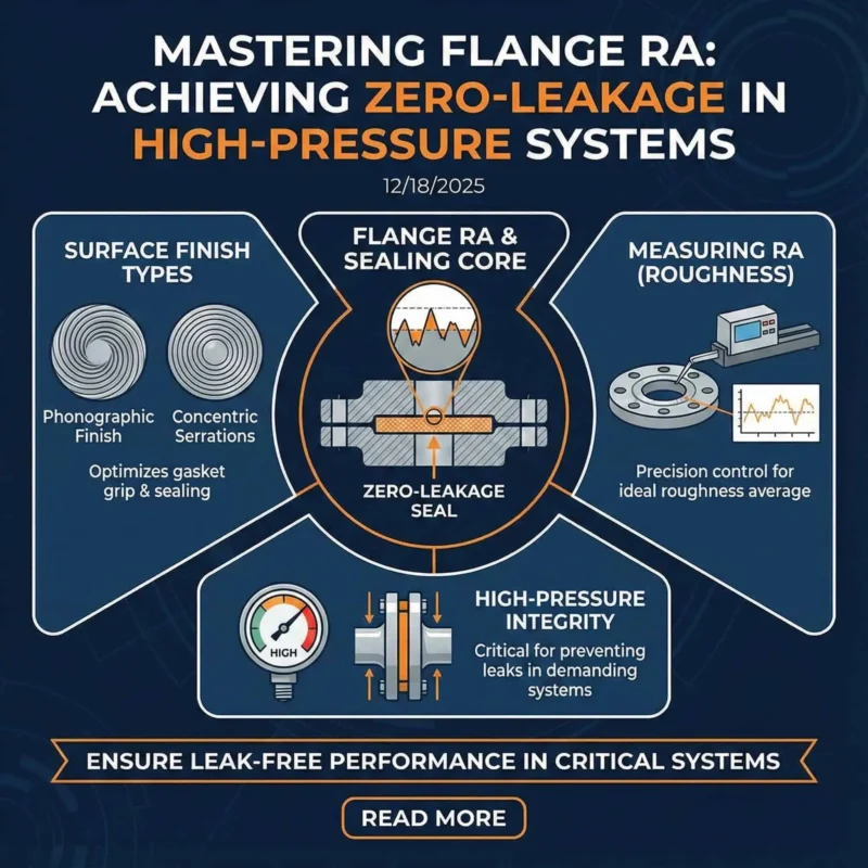
Flange Facing Types
When you select a flange, you also need to choose the right flange face. Flange faces are the surfaces where the gasket sits and creates a seal between two flanges. The type of face affects sealing performance, installation, and cost. A good rule: the flange face controls how gasket stress is generated and maintained — and that controls whether a joint survives vibration and thermal cycles.
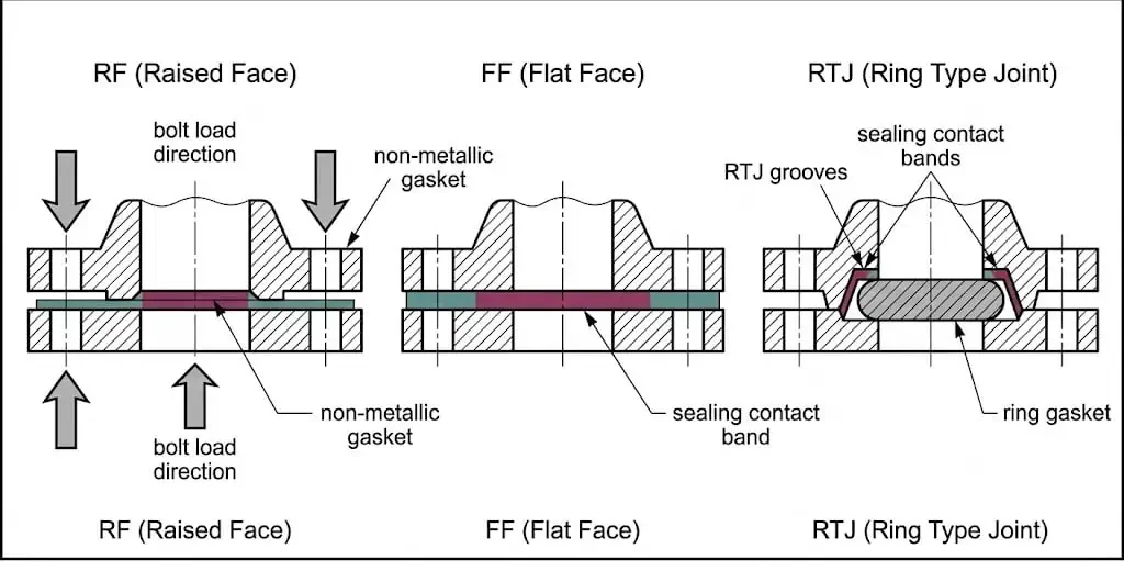
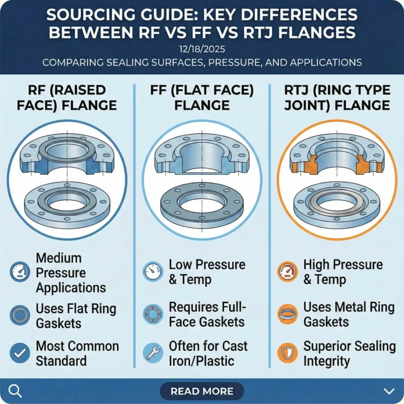
Raised Face (RF)
Raised face (RF) is the most common flange face for industrial piping.
You see a small raised area around the bore where the gasket fits. This design helps concentrate pressure on the gasket, making a tight seal. Raised face flanges work well in high-pressure and high-temperature systems.
Tip: Raised face flanges handle vibration and thermal cycling better than other types when the joint is correctly preloaded and supported.
| Flange Type | Advantages | Disadvantages |
|---|---|---|
| Raised Face (RF) | Robust, leak-proof seal; self-energizing under pressure; suitable for high pressure and temperature; resists vibration | Higher cost; needs skilled installation; gaskets are single-use; groove can trap debris |
Flat Face (FF)
Flat face (FF) flanges have a flat, even surface for the gasket.
You use flat face flanges in low-pressure systems or when you connect to cast iron or non-metallic equipment. The flat surface prevents over-tightening, which can damage brittle materials.
- Flat face flanges are easy to align.
- You often find them in waterworks and low-pressure applications.
Ring Type Joint (RTJ)
Ring type joint (RTJ) flanges use a metal ring gasket that fits into a machined groove.
You choose RTJ when you need a strong, leak-proof seal in extreme pressure or temperature conditions. The metal-to-metal seal gives you extra security in critical systems. Engineering check: ring material and hardness must be compatible with groove material to avoid galling or poor seating.
- RTJ flanges require precise installation.
- You must replace the gasket each time you open the joint.
Other Facings
Other flange faces include tongue and groove, male and female, and custom designs.
You use these special flange faces when you need extra alignment or sealing features. They are less common but solve unique challenges in some piping systems.
Remember, choosing the right flange faces helps you achieve a reliable, leak-free connection. Any face type still fails if bolt preload is uneven or the flange is forced into alignment.
Flange Materials in Piping
Stainless Steel Flanges
Stainless steel flanges offer the best corrosion resistance and durability for most piping systems.
You choose stainless steel when you need reliable performance in harsh environments, such as chemical plants or offshore platforms. In real plants, stainless selection is usually driven by corrosion mechanism: general corrosion, chloride pitting/crevice, stress corrosion cracking, or product contamination control (food/pharma). Sunhy’s stainless steel flanges stand out because they meet strict international standards and certifications. You benefit from products that follow ASME, ASTM, DIN, and EN requirements. Sunhy uses advanced CNC machining and precision forging, so you get flanges with tight tolerances and a perfect fit. You can select from a wide range of sizes and types, including slip-on, weld neck, lap joint, and blind flanges.
Sunhy’s stainless steel flanges carry certifications like ISO 9001, ISO 14001, and ISO 45001. These certifications show a strong commitment to quality, safety, and environmental responsibility.
| Certification/Standard | Description |
|---|---|
| ASME Certification | Ensures material, dimension, and performance criteria. |
| ISO Certification | Confirms international quality management. |
| ASTM Standards | Sets material and dimension requirements. |
| EN Standards | Meets European compliance. |
| PED Certification | Required for pressure equipment. |
| NACE Certification | For corrosive environments. |
| UL and API Certifications | For safety and oil/gas use. |
Carbon Steel and Alloy Steel
Carbon steel and alloy steel flanges are the most common choices for general industrial use.
You often select these flange materials for their strength and cost-effectiveness. Carbon steel works well in water, oil, and gas pipelines. Alloy steel gives you extra resistance to heat and pressure, making it suitable for power plants and refineries. Both types are easy to weld and machine, so you can use them in many applications. Engineering check: corrosion allowance, coating/lining strategy, and whether low-temperature toughness is required should be confirmed during material selection.
| Material Type | Description |
|---|---|
| Carbon Steel | Commonly used for various industrial applications. |
| Stainless Steel | Widely used for its corrosion resistance. |
| Nickel Alloy | Available for special requests and high-yield needs. |
Non-Metallic Flanges
Non-metallic flanges provide a lightweight and corrosion-resistant option for special applications.
You use these flange materials in systems that handle chemicals, acids, or water with low pressure. Materials like PVC, PTFE, and fiberglass reinforced plastic help you avoid rust and reduce weight. Non-metallic flanges are easy to install and maintain, but you should use them only where pressure and temperature are low. Engineering check: confirm bolt torque limits and flange rigidity — over-tightening can warp the face and create leaks.
When you select flange materials, always match the material to your system’s needs for safety and long-term performance.
Gasket Materials and Flange Selection
Types of Gaskets
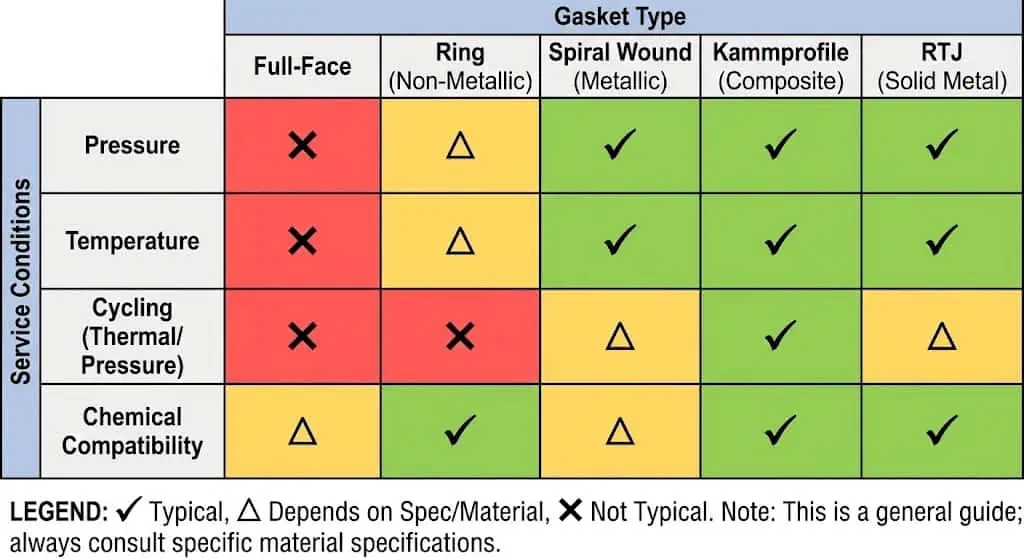
You need to select the right gasket type to ensure a leak-free flange connection.
Gaskets fill the small gaps between flange faces and help create a tight seal. The type of gasket you choose depends on the pressure, temperature, and media in your piping system. If the joint sees thermal cycling, pick gaskets known to tolerate relaxation and maintain sealing stress.
Common gasket types include:
- Full-Face Gaskets: Cover the entire flange surface. You use these in low-pressure water and utility systems.
- Ring Gaskets: Fit only around the pipe bore. These work best for higher pressure applications.
- Rubber Flange Gaskets: Flexible and easy to install. You often find these in plumbing and water treatment.
- Spiral Wound Gaskets: Handle high-pressure and high-temperature service. You see these in power plants and refineries.
- Corrugated Metal Gaskets: Durable and sometimes reusable. You use them in systems with frequent maintenance.
- Kammprofile Gaskets: Reliable under changing pressures and temperatures.
- Ring-Type Joint (RTJ) Gaskets: Designed for extreme conditions, especially in oil and gas.
You also need to consider gasket material:
- Nitrile Rubber (NBR): Used in automotive and petroleum industries (typical practice; verify chemical compatibility for your fluid).
- Neoprene Rubber: Good for outdoor and marine environments.
- EPDM Rubber: Durable in HVAC and water treatment (typically not used for hydrocarbons; confirm compatibility).
- Silicone Rubber: Withstands high temperatures in food and aerospace (confirm permeation and pressure limits).
- Santoprene TPV: Excellent chemical resistance (typical range depends on grade).
- Viton FKM: Handles high temperatures and chemicals (verify against amines/ketones where applicable).
- SBR Red Rubber: Moderate resistance to abrasion and weather.
Gasket Compatibility
You must match the gasket material to your system’s media and conditions for safe, reliable performance.
If you use an incompatible gasket, you risk leaks, blowouts, or chemical breakdowns.
Tip: Always check the chemical and temperature compatibility of your gasket with the fluid in your system. If your project has a gasket datasheet list, follow it — do not “substitute same thickness” without approval.
Key risks of poor compatibility:
- Leakage from improper sealing
- Sudden blowouts in high-pressure systems
- Chemical degradation, which can contaminate your process
| Risk | Description |
|---|---|
| Leakage | Gasket fails to seal, causing fluid to escape |
| Blowouts | Sudden failure under pressure, risking safety |
| Chemical Degradation | Gasket breaks down, leading to contamination |
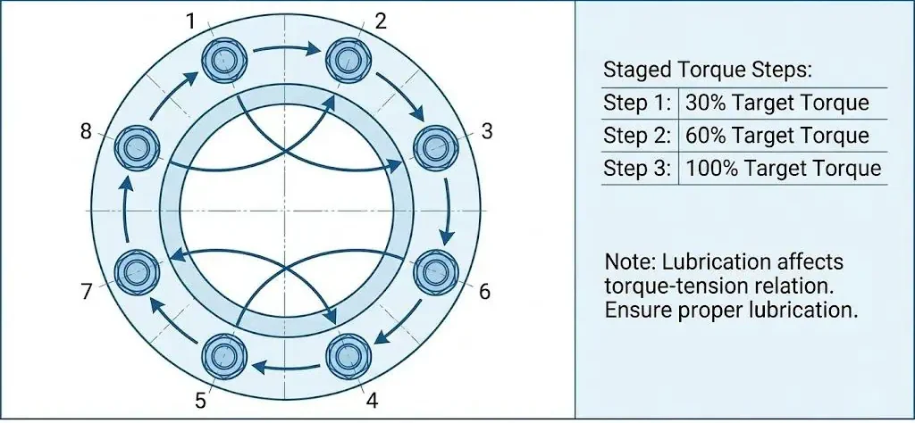
Bolting-up checklist (minimum practical steps):
- Clean flange faces; remove old gasket residue without gouging the face.
- Verify gasket type/size and center it; never “stretch” a spiral wound gasket to fit.
- Lubricate studs/nuts as specified; dry threads can give false torque.
- Tighten in a cross pattern in multiple increments (commonly 3+ steps), then a final rotational check if procedure allows.
You protect your piping system by choosing the right gasket type and material for your flange and application.
Always review your system’s requirements before making a selection.
How to Choose the Right Flange Type
Selection Criteria
You should always match the flange type to your system’s needs.
Choosing the right flange ensures safety, reliability, and long-term performance. Here are the main criteria you need to consider:
- Flange Type: Select from slip-on, weld neck, blind, socket weld, lap joint, or threaded flanges based on your application.
- Material: Pick materials like stainless steel, carbon steel, or specialty alloys to match the fluid, temperature, and environment.
- Size: Make sure the flange size fits your pipe and gasket for a secure connection.
- Classification: Check standards such as ASME or ASTM to ensure compatibility and performance.
- Thickness: Choose a flange with enough thickness to handle your system’s pressure.
- Bolt Holes: Confirm the number and size of bolt holes match your pipe and pressure class.
- Pressure Class: Verify the flange can safely handle your system’s pressure and temperature envelope.
Tip: Always review your system’s pressure, temperature, and fluid type before making a final choice. If the line sees vibration or cyclic load, include supports and joint geometry in your decision — not only flange class.
Common Mistakes
You can avoid most flange problems by watching for these common mistakes.
Mistakes during selection or installation can lead to leaks, failures, or safety hazards.
- Selecting the wrong material can cause corrosion or compatibility issues with the fluid.
- Using the incorrect flange size may result in leaks or poor performance.
- Failing to check compliance with safety standards can create health risks.
- Choosing unsuitable gasket materials often leads to leaks and unsafe conditions.
- Improper bolt tightening can distort flange faces and cause gasket failure.
- Misalignment during assembly increases the risk of leaks.
How to prevent these mistakes:
| Mistake | Prevention Tip |
|---|---|
| Wrong material | Match material to fluid and environment |
| Incorrect size | Double-check pipe and gasket dimensions |
| Ignoring standards | Use certified, standard-compliant flanges |
| Poor gasket selection | Choose gaskets for pressure and media |
| Improper bolt tightening | Follow recommended torque procedures |
| Misalignment | Align flanges carefully during installation |
Leak troubleshooting mini-flow (field usable):
- Step 1: confirm leak path — gasket OD, bolt hole weep, thread leak, or face scratch.
- Step 2: check alignment — if bolts are “pulling” the flanges together, fix alignment before re-gasketing.
- Step 3: inspect faces — radial scratches across sealing path, pitting, or embedded debris.
- Step 4: confirm gasket type and size — wrong ID/OD is a common hidden cause.
- Step 5: redo bolt-up — cross pattern, multiple increments; do not exceed torque limits for non-metallic flanges.
Note: Always use new, properly sized gaskets and follow installation best practices for a leak-free, reliable system. If a joint has leaked, treat it as an investigation item — not just “tighten more.”
Different Types of Pipe Flanges in Industry
Industry Standards
You must follow recognized industry standards when selecting different types of pipe flanges.
These standards ensure that the types of flanges you use will fit and perform safely in your piping system. Each standard sets rules for dimensions, materials, and pressure ratings. This helps you avoid compatibility issues and ensures reliable operation. For official references, ASME B16.5 and ASME B16.47 are the commonly used dimensional standards in “ANSI flange” projects, and AWWA standards may apply in waterworks service.
- ANSI: Sets dimensions, materials, and pressure ratings for compatibility.
- ASME: Focuses on mechanical strength and performance under pressure and temperature.
- DIN: German standard for flange compatibility.
- JIS: Japanese standard for flange compatibility.
You often see these standards referenced in project specifications. They help you compare the types of flanges available and choose the right one for your needs. When in doubt, confirm the piping class sheet, MTO description, and the flange standard in the isometric.
Here are some common flange standards you might encounter:
- ANSI Flange (ASME B16.5)
- ASME Flange (ASME B16.47 Series A and B)
- Industry Standard Flange (ASME B16.1)
- AWWA Flange
Custom and Standard Solutions
You can choose between standard and custom-engineered flange solutions based on your project requirements.
Standard flanges work well for most applications, but sometimes you need a custom solution for unique challenges: non-standard thickness, special facing detail, overlay/cladding, tighter tolerances, or special material compliance. Sunhy offers both options, so you always find the right fit for your system.
| Feature | Custom-Engineered Flanges | Standard Flanges |
|---|---|---|
| Quality | Superior quality with strict manufacturing standards | Varies, may not meet high standards |
| Fit | Custom-made for precise dimensions | Standard sizes may not fit perfectly |
| Corrosion Resistance | Designed for high resistance to corrosion | May not be suitable for aggressive environments |
| Pressure and Temperature Endurance | Engineered for high pressures and extreme temperatures | Limited endurance capabilities |
| Industry Compliance | Complies with international standards | May not meet all industry standards |
You benefit from custom flanges when your system faces extreme conditions or requires special dimensions. Standard flanges offer quick availability and cost savings for common uses. Sunhy’s expertise covers all types of flanges, including custom designs for demanding environments. You can rely on Sunhy to supply both standard and custom-engineered solutions that meet global standards.
When you understand the different types of pipe flanges and their industry standards, you make better choices for safety and performance.
You need to choose the right flange type, facing, and material for safe and reliable piping. Each flange serves a unique purpose. Weld neck flanges work best for high pressure and cyclic load. Slip-on flanges fit low-pressure systems. Always match the flange to your application.
- Select the correct flange type for your system.
- Pick materials that resist corrosion and suit your fluid.
- Check pressure ratings and size for a proper fit.
- Balance cost with long-term reliability.
For expert advice and quality products, consult trusted manufacturers like Sunhy.
FAQ
What is the most common flange type in piping systems?
Slip-on and weld neck flanges are the most common.
You often use slip-on flanges for low-pressure systems. Weld neck flanges work best for high-pressure or high-temperature applications. Both types provide reliable connections in many industries. In plants with vibration or thermal cycling, weld neck is commonly preferred for higher reliability.
How do you select the right flange material?
Match the flange material to your fluid, temperature, and environment.
You should choose stainless steel for corrosion resistance. Carbon steel fits general use. For special chemicals, consider non-metallic or alloy flanges. If sour service or chloride SCC risk exists, confirm compliance requirements and corrosion mechanism before finalizing material.
Can you reuse gaskets when installing flanges?
You should not reuse gaskets.
Gaskets lose their sealing ability after use due to compression set, creep, and surface damage. Always install a new gasket to ensure a leak-free connection and maintain system safety.
What standards should you check before buying flanges?
Check ASME, ASTM, DIN, or EN standards.
You must verify that your flanges meet recognized industry standards. This ensures proper fit, pressure rating, and safety in your piping system. For “ANSI flange” projects, confirm whether the dimensional system is ASME B16.5 (common sizes) or ASME B16.47 (large diameter).
When do you need a custom flange solution?
You need a custom flange for unique sizes or extreme conditions.
If your project requires special dimensions, high pressure, unusual materials, overlay/cladding, or special facing details, you should request a custom-engineered flange from a trusted manufacturer.
How do you tighten flange bolts to reduce leak risk?
Use a cross pattern and multiple torque increments.
In practical field procedures, the final torque is typically reached in 3 or more even steps (for example 30% → 60% → 100%), followed by a final check, using calibrated tools and the specified lubricant/condition. Always follow your project procedure and gasket manufacturer guidance.
Can you mix different flange face types (RF vs FF vs RTJ) in one joint?
No—mating faces must be compatible.
RF-to-FF mismatch can overload the gasket area or damage brittle equipment; RTJ requires matching grooves and correct ring. If you face a mismatch, correct the hardware rather than “torque harder.”