
The main difference between a blind flange and a Spectacle Blind Flange is where they are used and how isolation is achieved.
A blind flange is typically an end closure (solid plate, no bore) bolted to a pipe end or nozzle. A spectacle blind is an operational line blank installed between two flanges, allowing operators to change between “open” (spacer) and “closed” (blank) positions with clear visual confirmation. In practice, the safer choice is the one that matches your isolation philosophy (positive isolation vs. end closure), maintenance frequency, and the joint’s pressure–temperature and gasket/bolting constraints.
In industry, both appear across:
- Oil and gas: line isolation for maintenance windows, blind flange end closures on nozzles and tie-in points
- Chemical processing: isolation of hazardous fluids where visual status matters
- Power generation: steam/water services with strict bolted-joint control
- Water treatment: periodic isolation and equipment changeout
| Feature | Spectacle Blind (Line Blank) | Blind Flange (End Closure) |
|---|---|---|
| Structure | Two discs joined by a bridge (blank + spacer) | Single solid plate (no bore) |
| Isolation Function | Provides positive isolation between flanges; position is visually obvious | Seals a pipe end/nozzle; not an “in-line” open/close device |
| Use Case | Frequent or scheduled isolation points (turnarounds, equipment swap) | Permanent closure, hydrotest ends, spare nozzles, future expansion points |
| Installation | Remains in-line; requires bolt-length check for both positions | Bolted once; removal is a full disassembly event |
| Common pairing | Gasket selection and controlled assembly are critical to prevent fugitive leaks | Gasket selection and controlled assembly are critical to prevent fugitive leaks |
Important clarification: “Spade & spacer” (paddle blanks) are also line blanks under the same family of applications. A spectacle blind is essentially the combined, rotatable form used when operators want quick switching and unambiguous visual status.
Operators should always consider the system’s isolation requirement (positive isolation vs. end closure), the gasket type, and the bolting/torque procedure before making a selection.
Blind Flange Overview
What Is a Blind Flange?
A blind flange is a solid, single-piece plate used to seal the end of a pipe or nozzle.
This type of flange does not have a center opening. It blocks off flow by providing a bolted pressure boundary at an end connection. In design documents, blind flanges are commonly specified under pipe flange standards (for example, ASME B16.5 for NPS 1/2–24) and are selected by pressure class/PN, facing (RF/FF/RTJ), and material.
| Feature | Blind Flange | Other Flanges |
|---|---|---|
| Design | Solid plate, no bore | Opening for connections |
| Function | Seals pipe end/nozzle (end closure) | Joins pipes, valves, instruments, or equipment |
| Applications | End isolation, maintenance boundary, hydrotest end, future tie-in | Connecting piping sections |
Sunhy manufactures stainless steel blind flanges from dual-certified 316/316L forgings. From an engineering QA standpoint, what matters most is: heat/lot traceability (MTR), correct solution heat treatment for austenitic stainless, dimensional compliance to the specified standard, and the gasket facing finish required by the project specification.
Field example (selection mistake): A maintenance team ordered a blind flange “Class 300” but installed it on an RTJ joint that required an RTJ groove. The flange seated, but the gasket could not be properly energized and seepage appeared during warm-up. The fix was not “more torque”—it was the correct facing (RTJ) and gasket selection, then reassembly using a controlled bolting procedure.
Function and Use Cases
A blind flange provides a permanent or temporary end closure for pipelines and equipment nozzles.
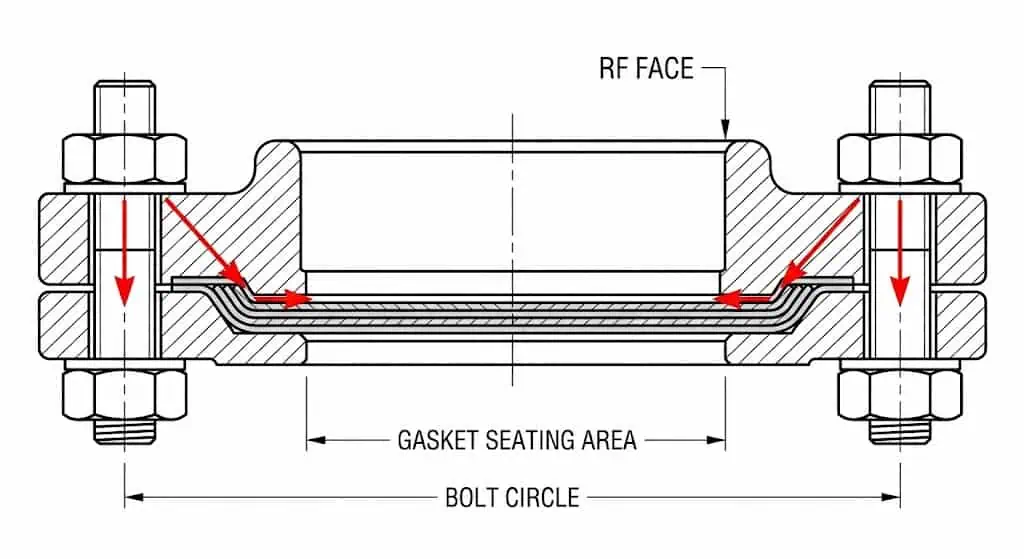
Operators use it to stop flow at a termination point during repairs, isolate an unused branch/nozzle, or create a pressure boundary for testing. In real plants, leak-free performance depends less on “thickness” and more on the bolted joint system: flange facing condition, gasket type, bolt material/condition, lubrication, alignment, and tightening method (multi-pass + star pattern). Assembly guidance for pressure-boundary bolted flange joints is commonly managed under flange-joint procedures aligned with recognized guidance (for example, ASME PCC-1).
Common use cases include:
- Isolating pipe ends for planned maintenance (end closure)
- Sealing off unused nozzles on pressure vessels and heat exchangers
- Hydrotest and pneumatic test boundaries (with extra attention to stored energy and test safety)
The following table shows typical standard families used when specifying blind flanges (always verify the project standard and size range):
| Standard | Code / Designation | Size Range | Pressure Class / PN | Face Types |
|---|---|---|---|---|
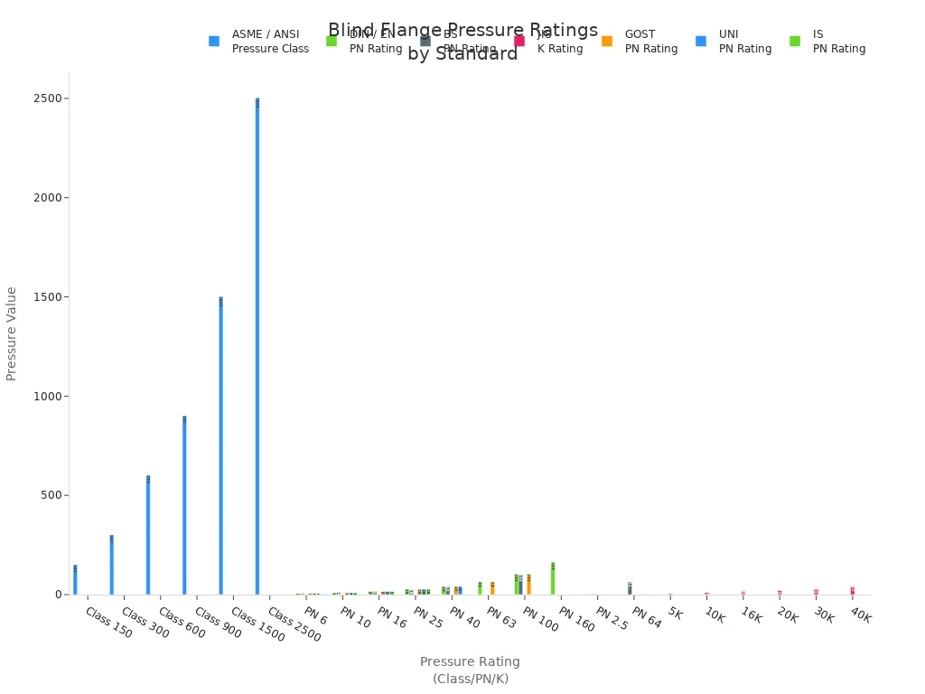
| ASME / ANSI (USA) | ASME B16.5 | NPS 1/2 – 24 | Class 150, 300, 600, 900, 1500, 2500 | RF, RTJ, FF, T&G, M&F |
| ASME (Large Diameter) | ASME B16.47 | NPS 26 – 60 | Class 75, 150, 300, 400, 600, 900 | RF, RTJ (per series and spec) |
| DIN / EN (Europe) | DIN 2527 / EN flange families | DN ranges per series | PN series per spec | RF, FF, T&G (per spec) |
| JIS (Japan) | JIS B2220 | Size ranges per series | K series per spec | FF, RF |
Field example (leak troubleshooting): A blind flange on a brine line showed “random” weeping after bolt-up. The root cause was crevice/pitting initiation under gasket seating stress combined with chloride exposure and a rough/contaminated facing. Corrective actions: replace gasket, clean and inspect the facing, verify flange finish, consider gasket type suited to the service, and tighten using a controlled, documented multi-pass procedure.
Practical bolt-up checklist (works for both blind flanges and line blanks):
- Confirm facing type (RF/FF/RTJ) matches the mating flange and gasket standard (for metallic gaskets, see ASME B16.20).
- Check flange alignment (parallel and concentric). Misalignment consumes bolt load and reduces gasket stress.
- Verify bolt/stud and nut grade per specification (common bolting standards include ASTM A193 for studs and ASTM A194 for nuts) and confirm usable thread engagement.
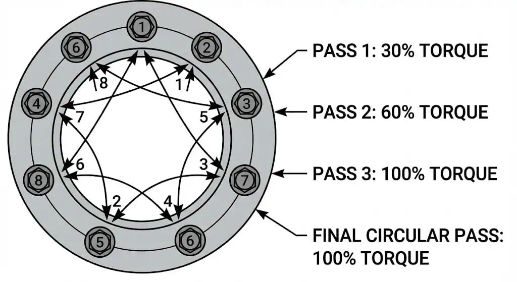
- Use a controlled tightening method: snug, then 30%/60%/100% torque in a star pattern; final rotational pass around the flange.
Typical Applications
Blind flanges are used wherever a secure, inspectable end closure is required.
They are common in high-consequence services, but they do not replace positive in-line isolation when the process safety requirement is “line blanking” between two flanges.
- Oil and gas pipelines (end closures, tie-ins, spare nozzles)
- Chemical processing plants
- Power generation facilities
- Water treatment systems
- Marine and shipbuilding
| Industry | Application Description |
|---|---|
| Oil and Gas | End closures on headers/nozzles; hydrotest boundaries; future expansion points (verify class/material tables to the governing code). |
| Marine | Corrosion-focused end closures; pay attention to crevice corrosion risk and gasket selection. |
| Chemical Processing | Hazardous fluid boundaries; bolted joint integrity procedures reduce fugitive emissions. |
| Power Generation | Steam/water systems; thermal cycles can relax bolts—use controlled assembly and inspection intervals. |
| Agriculture | Utility piping and manifolds where end closures simplify maintenance and seasonal shutdown. |
Blind flanges are commonly specified under ASME B16.5 for NPS 1/2–24, and under ASME B16.47 for NPS 26–60 when large-diameter flanges are used. Temperature suitability is not a single number: allowable pressure–temperature ratings depend on the governing standard and the material stress tables, and sealing performance depends on gasket and bolting choices. Austenitic stainless steels are widely used because they remain ductile at very low temperatures and offer strong general corrosion resistance, but chloride service and crevices require additional caution.
Tip: If “positive isolation” is required for lockout/tagout or process safety, specify a line blank (spectacle blind, spade/spacer) between flanges rather than relying on an end blind flange located elsewhere in the system.
Spectacle Blind Flange Overview
What Is a Spectacle Blind Flange?
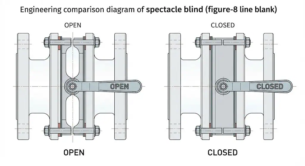
A spectacle blind flange is an operational line blank used for pipeline isolation between two flanges.
It consists of two metal disks connected by a small bridge (often called a “figure-8”). One disk is solid (blank) and blocks the line; the other is a spacer with a bore matching the line. Operators rotate it so the required disk aligns with the pipeline. Standards for line blanks (including spectacle blinds) define dimensional and rating requirements for installation between ASME B16.5 flanges.
- The solid disk provides positive isolation when installed in the “closed” position.
- The open disk (spacer) aligns with the pipe bore for normal operation.
- The connecting bridge keeps both disks together and supports clear marking/visual status.
Sunhy manufactures spectacle blind flanges with stainless steel materials. Engineering checks should focus on: dimensional compliance to the specified line blank standard, correct thickness class/rating, marking/identification that prevents wrong-position operation, and a flange-joint procedure that controls gasket stress.
Field example (operational error prevention): After a turnaround, a line was returned to service with the spectacle blind left in the “blank” position because the bridge marking was obscured by insulation and paint. The prevention measure was procedural and physical: tag the handle/bridge with “OPEN/CLOSED,” keep the bridge visible, and add a verification step in the line-up checklist.
Function and Use Cases
Spectacle blinds provide operational flexibility and visual confirmation of line status.
They are commonly used where operators need planned isolation points without removing the device from the joint. This reduces downtime, but it does not eliminate the need for safe depressurization, draining, and confirmation of zero energy before changing position. For leak-tightness, the same bolted-joint fundamentals apply: facing condition, gasket selection, bolt condition, lubrication, and a controlled tightening method (recognized guidance exists for pressure boundary flange joints).
| Benefit | Description |
|---|---|
| Safety | Supports disciplined flange-joint assembly to reduce leakage risk in critical service. |
| Convenient Maintenance | Provides a repeatable isolation point between flanges when planned work is frequent. |
| Visual Verification | Bridge/handle position allows quick confirmation of “open” vs “blanked,” reducing lineup ambiguity. |
| Reduces Unnecessary Disassembly | Remains in the joint; changeover is position-based rather than removal-based. |
| Versatility | Applicable across many fluids/gases when the rating/material/gasket match the service. |
Sunhy’s spectacle blind flanges should be supplied with traceability documentation as required by the project (heat number, MTR, and any required PMI/NDE). In critical service, many sites also require personnel competency controls for flange assembly and leak testing.
Typical Applications
Spectacle blinds are common where frequent isolation and unambiguous visual status are required.
They are often placed at equipment inlets/outlets, bypass lines, and locations used for periodic inspection or cleaning.
| Industry | Typical Service Conditions |
|---|---|
| Oil and gas industry | Frequent isolation for maintenance and leak risk management (site procedures typically reference flange-joint best practices). |
| Chemical and petrochemical | Hazardous fluids; positive isolation points reduce the chance of inadvertent flow during work. |
| Power generation | Steam/water systems; thermal cycles demand controlled assembly and inspection. |
| Pharmaceutical industries | Cleanability and procedural verification; position marking and documentation matter. |
| Marine and ship building | Space constraints; weight/handling planning is often required at larger sizes. |
| Water treatment plants | Regular maintenance and replacement work; visual confirmation helps reduce lineup mistakes. |
Tip: Treat the spectacle blind as part of a controlled isolation process. Marking, visibility, and a documented bolt-up method are as important as the metal itself.
Blind Flange vs. Spectacle Blind Flange Comparison
Design and Structure
The key difference is functional: a blind flange is an end closure, while a spectacle blind is an in-line line blank installed between two flanges.
A blind flange is a circular plate without a bore. It seals the end of a pipe or vessel nozzle. A spectacle blind is two discs joined by a bridge—one blank and one spacer—used for in-line isolation and flow restoration by rotation. Because the spectacle blind sits between two flanges, bolt length, gasket compression, and alignment checks are often more sensitive than on an end blind.
| Feature | Spectacle Blind Flange | Blind Flange |
|---|---|---|
| Structure | Blank + spacer joined by a bridge | Solid disc, no bore |
| Function | Positive isolation or open flow between flanges | Seals end of pipe/nozzle |
| Visual Confirmation | Bridge/handle indicates open/closed status | No in-line open/closed indication |
Sunhy uses precision machining for both types. From a field reliability standpoint, consistency of facing finish, flatness, and marking/traceability are the items that typically show up during leak investigations.
Operation and Switching
Blind flanges require removal to restore flow; spectacle blinds change position within the joint.
To “open” a line closed by a blind flange, the blind must be unbolted and removed—this is a full break of the pressure boundary. A spectacle blind is changed by rotating the device so the spacer aligns with the bore, then reassembling with the correct gasket stress and bolt load. The operational advantage is real, but the safety requirements remain: isolate, depressurize, drain/vent, verify zero energy, then proceed.
- Blind flange: Removal and reinstallation is required to change status.
- Spectacle blind flange: Position change is possible without removing the device from the line, but the joint still must be safely opened and reassembled.
Field example (bolt-up control): A unit reported recurring “first start” leaks after turning a spectacle blind back to open. The root cause was single-pass tightening at full torque. Switching to a documented multi-pass star-pattern procedure (and controlling lubrication consistency) stabilized joint performance.
How to Install Spectacle Blinds (ASME B16.48 Requirements)
Blind flanges and spectacle blinds both depend on correct gasket selection, alignment, and controlled tightening to prevent leaks.
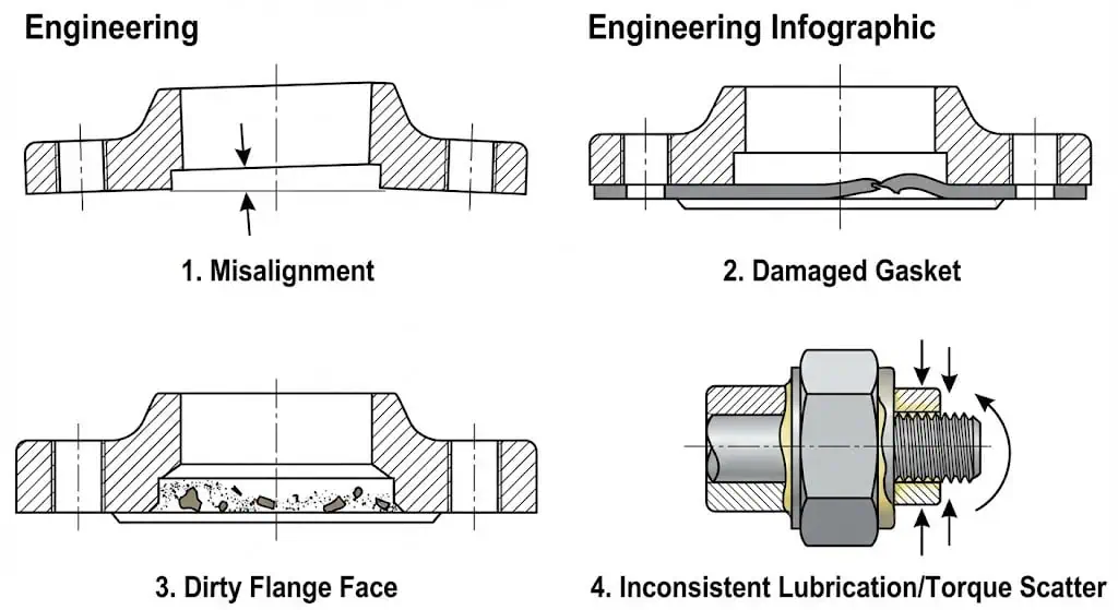
Many leak incidents trace back to gasket damage, flange misalignment, inconsistent lubrication, or uncontrolled torque-to-tension scatter—not “bad metal.” Recognized joint assembly guidance exists and is commonly referenced in plant flange management programs.
Proper installation of a blind flange involves:
- Confirming facing type matches the mating flange and gasket
- Cleaning and inspecting facing for damage and embedded debris
- Verifying bolt/stud grade and nut grade, and that threads run freely
- Applying a controlled tightening method (multi-pass + star pattern) and documenting final values
Spectacle blind flanges also require:
- Clear marking of open/blank positions and keeping the bridge visible
- Checking bolt length for both positions (blank vs spacer thickness) to maintain thread engagement
- Ensuring the line is not in bending (alignment and support) before bolt-up
| Flange Type | Installation Procedures | Maintenance Requirements |
|---|---|---|
| Blind Flange | Facing/gasket match, alignment, controlled tightening, test boundary controls | Periodic leak checks, corrosion/crevice inspection in aggressive services |
| Spectacle Blind Flange | Position marking, bolt-length verification, controlled tightening after each switch | Position verification, joint inspection after thermal cycles, bolt condition monitoring |
For gasket installation and bolted joint integrity, many sites also reference association guidance (for example, ESA/FSA installation procedures) alongside internal procedures.
Space, Weight, and Handling
Blind flanges are compact; spectacle blinds require more envelope and handling planning due to the bridge and dual-disc geometry.
A blind flange’s simple structure can be easier to handle and install, particularly in congested racks. A spectacle blind has extra width at the bridge and may interfere with insulation, supports, or adjacent piping. For larger sizes, plan lifting points, sling angles, and a safe placement method to prevent flange face damage.
- Blind flange: Compact; fewer interference issues.
- Spectacle blind flange: Bulkier; bridge clearance and safe handling become design inputs.
Sunhy offers both types in a range of sizes. For retrofit work, confirm the available swing/clearance for the bridge before selecting a spectacle blind as a direct “swap” for other isolation methods.
Cost Factors
Blind flanges often have lower unit cost than spectacle blinds because the geometry is simpler.
However, total cost is rarely just purchase price. If a joint must be opened repeatedly for maintenance, the labor hours, outage cost, and leak risk may dominate. Spectacle blinds can reduce repeat disassembly complexity, but they still require disciplined assembly each time to avoid fugitive leakage events.
| Flange Type | Cost Considerations |
|---|---|
| Blind Flange | Lower unit cost; removal-based status change increases labor for frequent switching |
| Spectacle Blind Flange | Higher unit cost; can reduce repetitive disassembly complexity in maintenance-heavy service |
Note: The “right” choice is the one that meets the isolation requirement and can be assembled leak-tight repeatedly under your site’s flange management controls (procedure, tooling, competency, inspection).
Pros and Cons of Each Type
Blind Flange Advantages & Disadvantages
Blind flanges provide a simple, robust end closure—but access restoration is a full disassembly event, and joint integrity depends on assembly quality.
Advantages
- Creates a clear pressure boundary at a pipe end/nozzle.
- Supports hydrotest boundaries and planned future tie-ins.
- Compact geometry reduces clearance issues.
- Applicable across a wide range of standards/materials when correctly specified.
Disadvantages
| Disadvantage | Description |
|---|---|
| Limited Accessibility | Restoring flow requires breaking the joint and removing the blind—plan isolation, de-pressurization, and reassembly controls. |
| Leak Risk if Assembly is Uncontrolled | Misalignment, gasket damage, inconsistent lubrication, or single-pass tightening can cause weeping or blowout in severe cases. |
| Lifecycle Cost in Frequent-Switch Service | Repeated removal increases labor hours and increases the number of “make/break” leak opportunities. |
| Space for Tooling | Even though the part is compact, adequate wrenching clearance and safe handling space are still required. |
Tip: If leaks appear, avoid “just add torque.” Inspect facing, gasket type/condition, alignment, lubrication, and tightening sequence first.
Spectacle Blind Flange Advantages & Disadvantages
A spectacle blind flange provides positive isolation with visual confirmation, but requires clearance, correct bolt-length management, and disciplined reassembly after switching.
Advantages
- This flange provides a positive in-line isolation point with clear visual status (open vs blanked).
- It reduces lineup ambiguity during servicing and shutdowns.
- The design supports frequent or scheduled isolation points without removing the device from the line.
- Operators can reduce leakage risk through controlled flange-joint practices and verified isolation steps.
- It can reduce downtime when isolation changes are routine, provided procedures are followed.
- The flange can support temporary or semi-permanent closure strategies at defined locations.
Disadvantages
- The dual-disc structure adds weight and requires more space around the joint.
- Bolt length and thread engagement must be verified for both positions (blank vs spacer thickness).
- Handling and alignment require care to avoid bending loads and flange face damage.
Note: The spectacle blind is strongest when combined with: visible marking, a line-up verification step, and a controlled bolt-up method that reliably delivers gasket stress.
Blind Flange vs. Spectacle Blind Selection Guide
Application Criteria
Use a blind flange for end closure and infrequent status changes; use a spectacle blind for positive in-line isolation with frequent or procedural switching.
Selecting the right isolation method depends on:
- Confirm the governing flange/line-blank standard and size range (e.g., ASME B16.5 for NPS 1/2–24; ASME B16.48 for line blanks installed between B16.5 flanges).
- Verify pressure–temperature ratings by material class tables and the code basis for your system.
- Match material to the fluid and corrosion mechanism (chlorides, sour service, caustic, erosion).
- Decide whether you need positive isolation with visual confirmation at the joint.
| Decision Input | If “Yes” | If “No” |
|---|---|---|
| Need positive in-line isolation between two flanges? | Prefer spectacle blind / spade-spacer line blank | Blind flange may be sufficient as an end closure |
| Need frequent switching during turnarounds? | Spectacle blind is often operationally efficient | Blind flange is simpler if switching is rare |
| Limited clearance near joint? | Confirm bridge clearance; consider spade/spacer or alternate isolation | Blind flange end closure typically fits more easily |
| High leak consequence (toxics/flammables)? | Increase controls: procedure, trained personnel, inspection, documentation | Standard controls may be acceptable (per site policy) |
Sunhy offers both standard and custom flanges. For critical service, procurement and QA typically require: MTR traceability, dimensional inspection records, and verification that the forging/material specification matches the purchase order.
Safety and Maintenance
Both flange types require a joint integrity mindset: correct parts, correct method, and verification.
Safety and maintenance considerations include:
| Safety Factor | Description |
|---|---|
| Material Compatibility | Select materials to resist corrosion mechanisms expected in the fluid/service. |
| Size and Fit | Dimensional compliance and proper alignment reduce joint stress and leakage risk. |
| Pressure and Temperature | Confirm ratings using the governing standard and material stress tables for your design basis. |
Routine maintenance tasks:
- Inspect flanges and gaskets using documented installation practices (cleanliness, damage checks, correct gasket type).
- Clean sealing surfaces and confirm bridge/handle visibility on spectacle blinds.
- Check bolt condition (thread damage, corrosion, galling) and replace when needed.
- After thermal cycles, follow site rules for joint inspection and any allowed retorque practice (gasket-type dependent).
Sunhy’s flanges are commonly specified to comply with ASME/ISO/EN families depending on project requirements, with traceability expectations defined by the purchaser.
Cost and Practicality
Blind flanges can be cheaper at purchase; spectacle blinds can reduce operational disruption where switching is frequent.
Key cost drivers include:
| Cost Factor | Impact on Selection |
|---|---|
| Material | Alloy and stainless grades change corrosion resistance and cost. |
| Size | Larger diameters increase weight/handling and bolt-up effort; validate standard size range. |
| Pressure Rating | Higher class/PN increases thickness, bolting demand, and gasket requirements. |
| Manufacturing | Forgings (e.g., ASTM A182 families) are typical for pressure boundary integrity. |
In maintenance-heavy systems, the practical cost is often dominated by outage time and joint reassembly quality controls rather than unit price alone.
Tip: When in doubt, write the selection basis into the work pack: governing standard + rating + facing + gasket + bolting + tightening method + verification step. That prevents “same size, different joint” mistakes.
The main difference:
A blind flange seals the end of a pipe, while a spectacle blind flange provides a positive, visually verifiable in-line isolation point between two flanges.
| Feature | Blind Flange | Spectacle Blind Flange |
|---|---|---|
| Design | Solid, no opening | Two discs (blank + spacer) joined by a bridge |
| Functionality | End closure | In-line isolation with visual status |
| Application | Permanent or infrequent end isolation | Frequent or procedural in-line isolation |
Quick selection checklist:
- Confirm the governing standard and size range (B16.5 / B16.47 / B16.48 as applicable).
- Confirm gasket standard and type for the facing (e.g., metallic gasket families are covered under ASME B16.20).
- Verify bolting materials (e.g., ASTM A193 for studs, ASTM A194 for nuts) and thread engagement.
- Use a controlled assembly method and record final values; investigate leaks using a structured checklist rather than “more torque.”
Sunhy provides documentation and machining consistency; field leak performance is still driven by joint cleanliness, alignment, gasket choice, and controlled bolt-up.
FAQ
What is the main difference between a blind flange and a spectacle blind flange?
A blind flange is an end closure; a spectacle blind is an in-line line blank with visual open/closed status.
A blind flange blocks an end connection (pipe end or nozzle) and restoring flow requires removal. A spectacle blind sits between two flanges and can be switched between blank and spacer positions as part of a controlled isolation procedure.
When should operators choose a spectacle blind flange over a blind flange?
Choose a spectacle blind when you need positive in-line isolation and frequent or procedural switching with clear visual verification.
Typical triggers include planned maintenance points, turnaround isolation steps, or any situation where the work pack requires a visible isolation status at the joint. Confirm clearance, bolt length, and joint assembly controls before selecting it.
Are Sunhy’s stainless steel flanges suitable for high-pressure applications?
Suitability depends on the governing standard, pressure class, temperature, and material rating tables for the specific alloy.
Sunhy’s stainless steel flangesare commonly produced from forged stainless materials (often ASTM A182 families). Engineering acceptance should be based on specified class/PN, material certification (MTR), and compliance to the chosen flange standard rather than a generic “high pressure” claim.
How do operators maintain blind and spectacle blind flanges?
Use a joint integrity routine: inspect, clean, verify alignment, and reassemble using a controlled tightening method.
Maintenance includes checking facing damage, gasket condition, bolt condition (corrosion/galling), and leak indicators. For spectacle blinds, also verify the correct position marking/visibility and confirm bolt length/thread engagement when switching between blank and spacer.
What standards do Sunhy’s flanges meet?
It depends on the purchase order; common families include ASME B16.5/B16.47 for flanges and ASME B16.48 for line blanks, with material specs such as ASTM A182 for forgings.
For critical service, require the specific standard designation on the PO and verify marking, dimensions, and material certification during receiving inspection.


