")
You need accurate ANSI flange dimensions to ensure safe and efficient piping systems.
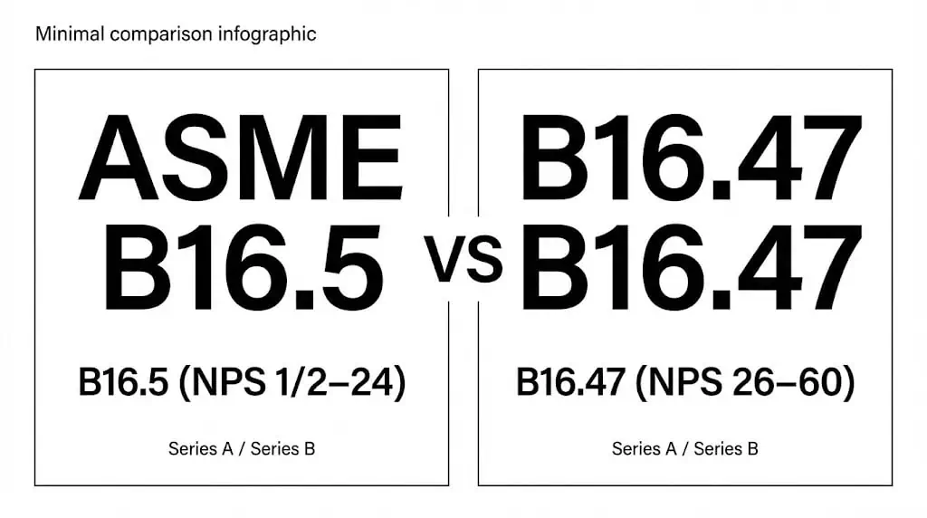
In most industries, “ANSI flanges” commonly refers to flanges made to ASME B16.5 (NPS 1/2″–24″) and ASME B16.47 (NPS 26″–60″). Always select flanges using the latest standard tables, because pressure-temperature ratings depend on material group and temperature—not just the class number.
If you need a fast starting point, use these internal references before you open the standard books:
- ASME B16.5 flange standard overview (sizes, classes, key terms)
- Class 150 vs Class 300 flanges (how class impacts selection)
- Stainless steel flange types & selection guide (type-by-type use cases)
- Key benefits of knowing ANSI flange dimensions:
- Prevents bolt-hole mismatch and assembly rework
- Improves gasket sealing reliability and joint life
- Reduces downtime from leaks caused by wrong class / wrong face / wrong bolting
| Benefit | Description |
|---|---|
| Corrosion resistance (stainless) | Stainless steels form a passive oxide film that helps resist rust in many industrial environments. |
| Strength at elevated temperature | Material choice + correct class selection supports hot service such as steam, hot oil, and process gas. |
| Hygienic and cleanable | Commonly used in pharma/food systems when surface finish and cleanability matter. |
| Manufacturing flexibility | CNC machining and controlled tolerances help keep bolt circle and faces consistent for assembly. |
Tip: Treat dimension tables as “must-follow” design inputs. A flange that is “almost the same” can still fail during bolt-up.
What Are ANSI Flanges?
ANSI Flanges Definition
ANSI flanges are standardized pipe flanges and flanged fittings designed for reliable connections in piping systems. You use these components to join pipes, valves, pumps, and equipment, creating a bolted gasketed joint intended to be leak-tight under the designed pressure and temperature conditions.
The history of ANSI/ASME standardization for flanges includes several important milestones:
- In 1920, the American Engineering Standards Committee formed Sectional Committee B16 to unify standards for pipe flanges and flanged fittings.
- By 1923, Subcommittee 3 began developing standards for steel pipe flanges for high-pressure service.
- In 1988, ANSI B16.5 received formal approval as an American National Standard.
Engineering note: Do not assume ASME B16.5 flanges are interchangeable with waterworks flange standards (such as AWWA). Always verify bolt circle, bolt-hole count, and face details before mating different standards.
Note: “ANSI flange” is a search term; the governing dimensional standards in modern projects are typically ASME B16.5 and ASME B16.47.
Industry Applications
You will find ANSI flanges in a wide range of industries due to their versatility and reliability. Typical sectors include:
- Oil and gas (upstream, midstream, downstream)
- Chemical processing and petrochemicals
- Power generation (steam, condensate, auxiliary systems)
- Water and wastewater facilities (verify standard compatibility before mating)
- Shipbuilding, offshore platforms, and marine systems
For practical selection help, you can cross-check flange type and typical use cases here: stainless steel flange types & selection guide.
Flange Types and Pressure Classes
Main Flange Types
You will encounter several main types of ANSI flanges, each designed for specific applications and installation methods.
Use this table as a field guide, then confirm final dimensions in the standard tables.
| Flange Type | Description | Applications |
|---|---|---|
| Threaded Flanges | Threads allow installation without welding. | Low-pressure, maintenance-heavy service. Avoid for severe vibration and high temperature. |
| Weld-Neck Flanges | Long-tapered hub welded to pipe for stress distribution. | High-pressure / high-temperature / cyclic service where fatigue resistance matters. |
| Slip-On Flanges | Slides over pipe, then welded in place. | General service where cost and installation speed matter. |
| Socket-Weld Flanges | Pipe inserts into socket before welding. | Small-bore high-pressure service (instrument lines, utilities), where alignment control is needed. |
| Blind Flanges | Solid plate to close off piping. | Isolation points, pressure testing, future expansion tie-ins. |
| Lap-Joint Flanges | Used with a stub end; allows easy alignment. | Frequent disassembly or expensive alloy piping (optimize flange material cost). |
Internal dimension references (useful when you need quick checks): weld neck flange and blind flange pages.
Tip: For vibration or thermal cycling, prioritize weld neck flanges + correct gasket + controlled bolt-up procedure.
Pressure Class Overview
The class of a flange defines an allowable pressure-temperature envelope, not a single fixed “psi value”.
Always use the standard pressure-temperature tables for your exact material group and service temperature. As temperature rises, allowable pressure typically decreases.
| Class | Where it’s commonly used | What to verify |
|---|---|---|
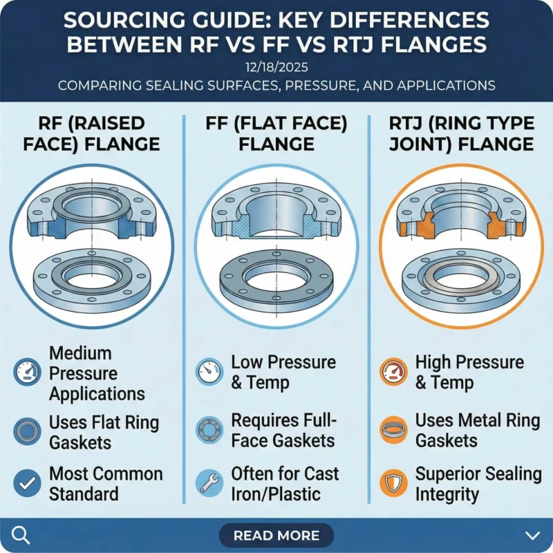
| 150 | General service utilities, low-to-moderate pressure | Gasket type, bolt grade, face (RF/FF) |
| 300 | Process lines with higher pressure or higher temperature | Material group + temperature derating |
| 600 | High-pressure process and energy systems | Bolting control, face finish, joint assembly procedure |
| 900 / 1500 / 2500 | Critical high-pressure service | Engineering review, stress, assembly plan, inspection |
")
Important: Charts like the above should be treated as a visual aid only. Final design must use the pressure-temperature ratings in ASME B16.5 / B16.47 for your exact material and temperature.
- Pressure classes such as 150, 300, and 600 define operating limits based on material and design.
- The pressure rating of the flange changes with fluid temperature—always check the official pressure-temperature tables.
- Use Class 150 vs Class 300 flanges as a practical primer for selection logic.
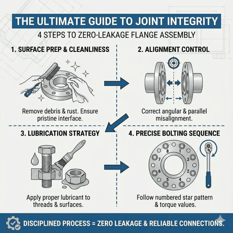
Note: Many real-world leaks are assembly-related (surface, gasket, bolt load control) even when the flange class is “correct”.
ANSI Flanges Dimensions
Key Dimensions Explained
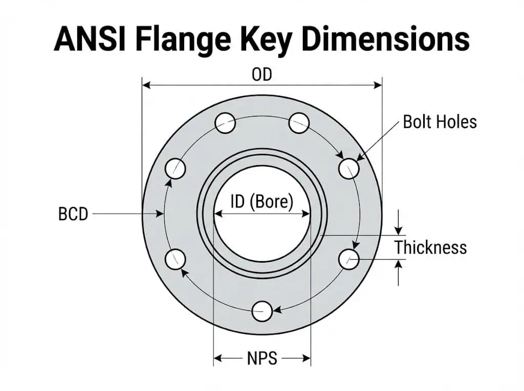
You must understand the key dimensions of ansi flanges to ensure proper fit and safe operation.
These parameters control interchangeability, sealing, and bolt-up success:
- Nominal Pipe Size (NPS): The pipe size the flange matches.
- Outer Diameter (O.D.): Total flange diameter.
- Inner Diameter (I.D.): Bore diameter (flow opening).
- Flange Thickness: Influences stiffness and pressure capability.
- Bolt Circle Diameter (BCD): Bolt pattern circle; must match mating flange.
- Number and Size of Bolt Holes: Affects bolt selection and joint load distribution.
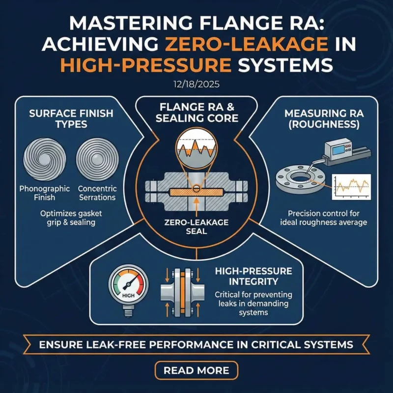
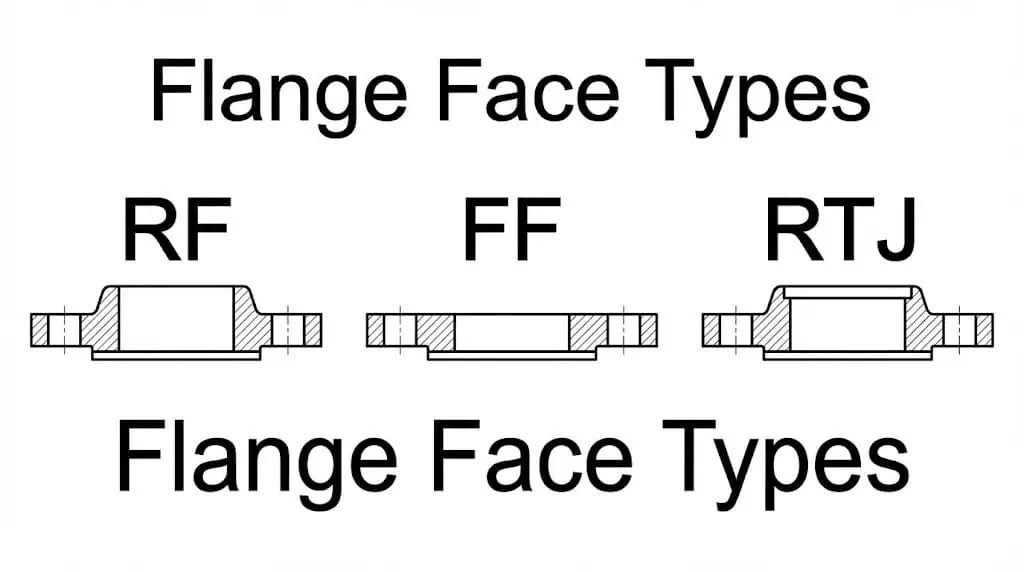
- Face Type: RF/FF/RTJ impacts gasket choice and sealing method.
Tip: Bolt circle mismatch is one of the fastest ways to waste field time. Verify BCD + bolt-hole count before purchasing.
You can see how these dimensions relate in the table below:
| Dimension | Importance |
|---|---|
| Outer Diameter (O.D.) | Ensures compatibility with adjacent components. |
| Inner Diameter (I.D.) | Matches pipe size for efficient flow. |
| Flange Thickness | Affects stiffness and sealing stability under bolt load. |
| Bolt Circle Diameter | Aligns bolt holes for secure assembly. |
| Number and Size of Bolts | Distributes load and helps prevent leaks. |
| Face Type | Controls gasket style and sealing method. |
| Pressure Rating | Defines allowable pressure-temperature envelope for the material group. |
Reading Dimension Tables
You need to read ansi flange dimension tables accurately to guarantee safety and compatibility.
Dimension tables typically include:
- NPS (Nominal Pipe Size)
- Flange O.D. (Outer Diameter)
- Flange Thickness
- Number of Bolts
- Bolt Hole Diameter
- Bolt Circle
Here is a practical example excerpt for quick checks (always verify in the standard tables and match flange type + face):
| NPS (inches) | Flange O.D. (inches) | Flange Thickness (inches) | No. of Bolts | Bolt Hole Diameter (inches) | Bolt Circle (inches) |
|---|---|---|---|---|---|
| 1/2 | 3.50 | 0.38 | 4 | 0.62 | 2-3/8 |
| 1 | 4.25 | 0.50 | 4 | 0.62 | 3-1/8 |
| 2 | 6.00 | 0.69 | 4 | 0.75 | 4-3/4 |
| 4 | 9.00 | 0.88 | 8 | 0.75 | 7-1/2 |
| 6 | 11.00 | 0.94 | 8 | 0.88 | 9-1/2 |
| 8 | 13.50 | 1.06 | 8 | 0.88 | 11-3/4 |
| 12 | 19.00 | 1.19 | 12 | 1.00 | 17.00 |
| 16 | 23.50 | 1.38 | 16 | 1.12 | 21-1/4 |
| 24 | 32.00 | 1.81 | 20 | 1.38 | 29-1/2 |
")
Note: Always verify each measurement against your flange type (WN/SO/BL), face (RF/FF/RTJ), and the governing standard tables before fabrication or ordering.
Example Dimension Table
You should always check ansi class ratings and pressure-temperature ratings when selecting flanges.
Bolt-hole count and bolt-hole diameter change with pressure class and size. Use this as a simplified illustration, then confirm in the standard:
| Pressure Class | Number of Bolt Holes | Diameter of Bolt Holes (mm) |
|---|---|---|
| Class 150 | 12 | 25.4 |
| Class 300 | 16 | 32 |
| Class 400 | 16 | 34.9 |
| Class 600 | 20 | 34.9 |
| Class 900 | 20 | 38.1 |
| Class 1500 | 16 | 54 |
| Class 2500 | 12 | 73 |
")
You must reference the correct standard for your application.
- ASME B16.5 typically applies to NPS 1/2″ to 24″ (pressure classes per the standard tables).
- ASME B16.47 applies to larger sizes (NPS 26″ to 60″) and includes Series A and Series B designs.
| Standard | Size Range (NPS) | Notes |
|---|---|---|
| ASME B16.5 | 1/2″ to 24″ | Most common “ANSI flange” dimensional reference in process industries. |
| ASME B16.47 | 26″ to 60″ | Large diameter steel flanges; verify Series A vs Series B before ordering. |
| Series | Description |
|---|---|
| Series A | Typically heavier duty; common in process piping. |
| Series B | Typically lighter/more compact; confirm bolt pattern compatibility. |
Alert: Always select flanges that comply with the governing standard and project specification. “Close enough” dimensions can create leaks, bolt binding, or gasket blowout.
Engineering example: A common site issue is mating a flange from a different standard (or wrong series) that “looks right” but has a different bolt circle. The result is rework, damaged studs, and delayed commissioning.
Accurate dimensions protect your piping system from leaks, failures, and costly downtime.
Consult standard tables before ordering, and keep records for traceability and QA.
Selecting ANSI Flanges
Selection Steps
You must follow a systematic approach to select the correct ANSI flange for your piping application.
- Gather project data.
Design pressure, design temperature, NPS, flange type, face type, and corrosion allowance. - Confirm the governing standard.
Use ASME B16.5 for common sizes; use ASME B16.47 for large diameter steel flanges. - Select flange material.
Match fluid chemistry, temperature, and required mechanical properties (example: 304/316 stainless for corrosion resistance; verify chloride risk). - Select pressure class.
Use pressure-temperature ratings for your material group and service temperature. - Confirm dimensions.
Verify bolt circle, bolt-hole count, flange thickness, and face details. - Select gasket + bolting.
Choose gasket style and bolt grade compatible with face type and temperature. - Define assembly method.
For critical service, follow a controlled bolt-up process such as ASME PCC-1 guidance. - Document and inspect.
Record heat numbers, lot numbers, and inspection results.
Tip: For critical joints, reference controlled flange joint assembly practices such as ASME PCC-1.
Selection example (field-ready):
If you have a hot process line with vibration, a typical robust choice is weld neck + raised face + appropriate spiral wound gasket + controlled bolt-up, then confirm final details in the governing standard tables and project specs.
Common Mistakes
You can avoid costly errors by understanding the most frequent mistakes in ANSI flange selection.
| Mistake | Consequence |
|---|---|
| Ignoring pressure-temperature ratings | Leaks, gasket failure, flange damage, downtime. |
| Using the wrong face type | Poor gasket seating, leakage, uneven compression. |
| Mating different standards/series without verification | Bolt-hole mismatch, forced assembly, damaged studs. |
| Reusing old gaskets | Loss of resilience, leaks after thermal cycles. |
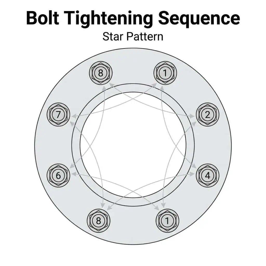
| Uneven bolt load / poor tightening method | Gasket blowout risk, repeat leaks, joint relaxation. |
- Never treat class as a single “psi value”. Use pressure-temperature tables.
- Replace gaskets during reassembly unless your project procedure explicitly permits reuse.
- Confirm face type (RF/FF/RTJ) and gasket compatibility.
- Use controlled tightening steps to reduce uneven gasket compression.
Note: Many repeat leaks come from bolt-load inconsistency rather than the flange itself. A controlled bolt-up process can dramatically reduce rework.
2025 Standards Tips
You must stay updated with best practices and project requirements for ANSI flange selection in 2025.
- Confirm which standard edition your project requires (B16.5 vs B16.47; Series A vs Series B).
- Verify flange face type and gasket style early (RF/FF/RTJ).
- Follow proper torque / tightening sequence to reduce uneven gasket compression.
- Inspect and maintain flanged joints; record leakage history and corrective actions.
- Keep traceability documentation (heat number, lot number) for QA audits and maintenance planning.
Alert: Following the governing standard and a controlled assembly method supports safety, reliability, and long joint life.
You can optimize your piping system by selecting the right ansi flanges, verifying accurate dimensions, and applying disciplined joint assembly practices.
Flange Markings and Compliance
Verifying Markings
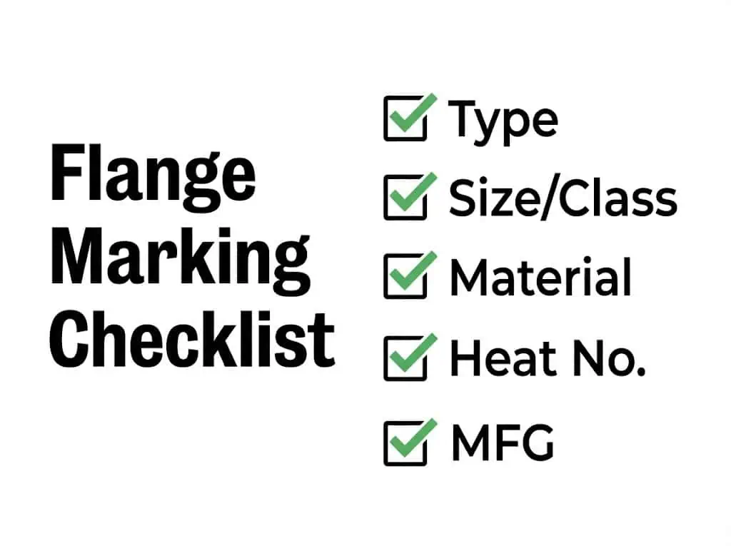
You must check flange markings to confirm authenticity and compliance with industry standards. Markings support traceability and help prevent incorrect installation. In many projects, flange marking practices reference industry marking standards such as MSS SP-25.
| Marking Type | Description |
|---|---|
| Flange Type Identification | Shows type such as WN / SO / BL for correct application. |
| Dimensional Identification | Lists size and class for correct fit and rating selection. |
| Material Identification | States material grade for corrosion and temperature compatibility. |
| Pressure Rating Identification | Indicates class (e.g., 150 / 300 / 600). |
| Manufacturer Identification | Displays manufacturer logo/code for traceability. |
You should also check for:
- Heat number (links to raw material batch)
- Lot number (tracks production batch)
- Clear, permanent marking location and legibility
Tip: Verify markings before installation. A wrong material grade can pass visual inspection but fail in corrosion or high-temperature service.
2025 Compliance
You need to ensure that flanges meet updated project requirements and global standards for 2025. The latest requirements often emphasize dimensional accuracy, material quality, and traceability.
| Standard | Description |
|---|---|
| ASME B16.5 | Common dimensional reference for many “ANSI flanges” used in process industries. |
| ASME B16.47 | Design specifications for large diameter steel flanges (verify Series A/B). |
| MSS SP-25 (marking) | Industry reference for marking systems supporting traceability. |
Sunhy supports compliance through controlled machining, inspection, and traceability documentation. You can also reference Sunhy’s standards overview here: ASME B16.5 flange standard.
Alert: Only select flanges with complete and legible markings, verified material documentation, and dimensions matching the governing standard tables.
You can select the right ansi flanges for your project by following a clear process.
Here are the essential steps:
- Prepare tools and materials (gaskets, studs, lubricants if permitted).
- Check standard compliance, markings, and flange face condition.
- Align, install bolts, and tighten using a controlled sequence.
- Pressure test / leak test per project procedure and record results.
Use this quick reference checklist for ansi flange selection:
| Criteria | Description |
|---|---|
| Compliance with standards | Confirm ASME B16.5 / B16.47 and project spec. |
| Pressure-temperature rating | Use official rating tables for the exact material and temperature. |
| Connection dimensions | Verify BCD, bolt holes, thickness, and face type. |
| Material selection | Match corrosion, temperature, and mechanical requirements. |
Always consult updated standards and verify markings. Correct interpretation prevents mismatch, supports traceability, and improves joint reliability.
FAQ
What is the significance of the Outside Diameter (O.D.) in ANSI flanges?
You must match the O.D. to your pipe or equipment for proper fit. O.D. helps ensure the flange clears adjacent components and seats correctly with the mating flange.
- Ensures compatibility
- Prevents assembly interference
- Supports secure connections
Which key dimensions should you consider when selecting ANSI flanges?
You should focus on these critical dimensions:
| Dimension | Purpose |
|---|---|
| NPS | Pipe size |
| O.D. | Flange fit |
| I.D. | Flow capacity |
| Bolt Circle | Bolt alignment |
| Thickness | Stiffness and sealing stability |
How does the number of bolt holes affect flange performance?
You need the correct number of bolt holes for even load distribution. Correct bolt pattern helps apply uniform gasket compression and reduces leak risk.
- Reduces leakage risk
- Maintains joint stability
- Supports system safety
How do you choose the right pressure rating for ANSI flanges?
You must select a pressure rating that matches your system’s requirements. Use pressure-temperature tables for the exact material group and service temperature, then confirm the correct flange dimensions and face type.
- Check design pressure and temperature
- Confirm governing standard (B16.5 vs B16.47)
- Confirm material compatibility and gasket/bolting plan
Are ASME B16.5 flanges interchangeable with AWWA flanges?
Not by default. Bolt circle diameter and bolt-hole patterns may differ across standards. Always verify dimensions before mating standards in the field.
What is the fastest way to prevent repeat flange leaks?
Control the basics: correct face + correct gasket + clean surfaces + uniform bolt load with a controlled tightening sequence. Many leaks come from uneven bolt load rather than wrong flange size.