Stainless Steel Blind Flanges
As a specialist manufacturer, Sunhy engineers high-integrity stainless steel blind flanges for the critical, high-stress task of sealing and isolating piping systems.
Unlike flanges designed for flow, a blind flange is a solid, non-bored disc that must safely absorb the full internal pressure of a line (acting as a high-stress mechanical seal). Our flanges are forged from premium SS316L and SS304L (per ASTM A182) to provide absolute containment in high-pressure, corrosive, or hygienic applications.
We manufacture to all relevant standards, including ASME B16.5 (up to 24″) and ASME B16.47 (for large diameters), ensuring every flange is delivered with a full EN 10204 3.1 MTR for guaranteed compliance and traceability.
Types of Blind Flanges We Supply
 Stainless Steel Flanges
By Design Type
By Standard & Class
Advanced Materials
8-Bolt Stainless Steel Blind Flange, Raised Face (RF)
Stainless Steel Blind Flange: Specifications & Material Analysis
Stainless steel blind flanges are the ideal choice when sealing a piping system against corrosion, at high pressures, or for hygienic applications (e.g., food processing). Unlike coated carbon steel, they provide long-term integrity with zero risk of contamination.
In-Depth Material Analysis: SS316L vs. SS304L
Choosing the correct stainless grade is critical. Both “L” grades (low carbon, max 0.03%) prevent “sensitization” (carbide precipitation) during welding of the mating flange, ensuring corrosion resistance is maintained at the joint.
- The Molybdenum (Mo) Difference: The key distinction is that SS316L contains 2-3% Molybdenum (Mo); SS304L does not.
- Use SS304L: A cost-effective solution for general-purpose applications (fresh water, food processing, industrial) where there is no chloride exposure.
- Use SS316L (ASTM A182-F316L): Mandatory for any marine, coastal, wastewater, or chemical processing application. The Molybdenum provides critical resistance to chloride pitting and crevice corrosion, preventing catastrophic failure in these harsh environments.
| Specification | Details |
|---|---|
| Size Range | NPS 1/2″ to NPS 48″ (DN15 to DN1200) |
| Pressure Class | ASME B16.5 (up to 24″): Class 150, 300, 600, 900, 1500, 2500 ASME B16.47 Series A/B (larger sizes): Class 150 – 900 |
| Material Grade | Stainless Steel: SS316/L (F316/L), SS304/L (F304/L) per ASTM A182 |
| Face Type | Raised Face (RF) – Most Common Flat Face (FF), Ring-Type Joint (RTJ) |
| Standards | ASME B16.5, ASME B16.47, EN 10204 3.1 |
Certification & Traceability: The EN 10204 3.1 MTR
For critical, high-pressure service, an EN 10204 3.1 Material Test Report (MTR) is essential. This is not just a spec sheet; it is your quality guarantee, providing:
Full Traceability: Links the flange directly to its “heat” or “melt” (the original metal batch).
Verified Chemistry: Certifies the exact chemical composition (e.g., proving the Mo content in SS316L).
Mechanical Properties: Verifies its strength (Tensile, Yield) and compliance with all ASTM/ASME standards.
Sunhy provides a full 3.1 MTR with every order, guaranteeing the material you ordered is the material you receive.
What is a Blind Flange
A threaded flange is a special type of pipe fitting that doesn’t need welding. It makes it easy to connect pipes, valves, or equipment together. This is done by making threads in the pipe and screwing it onto another pipe. Threaded flanges are mainly used for small-diameter pipes from DN15 to DN100. They are commonly used in applications where it is difficult to weld or where it is important that the system can be easily taken apart to ensure it is sealed properly and safely.

Blind Flanges Specifications
Standard Compliance & Scope
Our dimensions are strictly calibrated to ASME B16.5 for standard sizes (NPS 1/2″ to 24″) and ASME B16.47 Series A & B for large diameter applications (NPS 26″ to 48″). This dual-standard compliance guarantees precise mating with connecting flanges across all industrial pressure classes.
Material & Application
Available in premium Forged Stainless Steel grades SS304/304L and SS316/316L.
Function: Designed to hermetically seal the end of a pipe system, facilitating pressure testing and allowing easy access for future maintenance or expansion.
Integrity: Engineered to withstand maximum system pressure and thermal cycling.
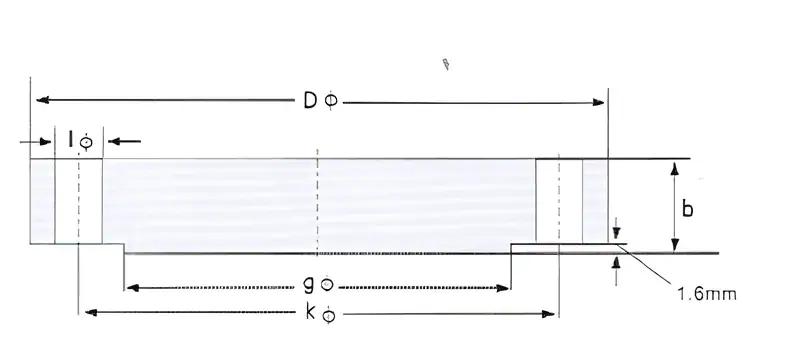
Dimensional Reference
Refer to the technical diagram to identify key geometric parameters:
D: Outside Diameter
k: Bolt Circle Diameter
b: Flange Thickness
g: Raised Face Diameter
Note: For sizes above 26″, please specify Series A (MSS SP-44) or Series B (API 605) to ensure bolt hole alignment.
Blind Flange (BL) Dimensions
Unit: Millimeters (mm)ASME B16.5 Class 150 Blind
| NPS (Size) |
Outside Dia (O) (mm) |
Thickness (t) (mm) |
Bolt Circle (BC) (mm) |
Holes (Qty) |
Bolt Size (Inch) |
|---|---|---|---|---|---|
| 1/2" | 88.9 | 11.2 | 60.5 | 4 | 1/2" |
| 3/4" | 98.6 | 12.7 | 69.9 | 4 | 1/2" |
| 1" | 108.0 | 14.2 | 79.2 | 4 | 1/2" |
| 1-1/2" | 127.0 | 17.5 | 98.6 | 4 | 1/2" |
| 2" | 152.4 | 19.1 | 120.7 | 4 | 5/8" |
| 3" | 190.5 | 23.9 | 152.4 | 4 | 5/8" |
| 4" | 228.6 | 23.9 | 190.5 | 8 | 5/8" |
| 6" | 279.4 | 25.4 | 241.3 | 8 | 3/4" |
| 8" | 342.9 | 28.4 | 298.5 | 8 | 3/4" |
| 10" | 406.4 | 30.2 | 362.0 | 12 | 7/8" |
| 12" | 482.6 | 31.8 | 431.8 | 12 | 7/8" |
| 16" | 596.9 | 36.6 | 539.8 | 16 | 1" |
| 20" | 698.5 | 42.9 | 635.0 | 20 | 1-1/8" |
| 24" | 812.8 | 47.8 | 749.3 | 20 | 1-1/4" |
ASME B16.5 Class 300 Blind
| NPS (Size) |
Outside Dia (O) (mm) |
Thickness (t) (mm) |
Bolt Circle (BC) (mm) |
Holes (Qty) |
Bolt Size (Inch) |
|---|---|---|---|---|---|
| 1/2" | 95.3 | 14.2 | 66.5 | 4 | 1/2" |
| 1" | 124.0 | 17.5 | 88.9 | 4 | 5/8" |
| 2" | 165.1 | 22.4 | 127.0 | 8 | 5/8" |
| 3" | 209.6 | 28.4 | 168.1 | 8 | 3/4" |
| 4" | 254.0 | 31.8 | 200.2 | 8 | 3/4" |
| 6" | 317.5 | 36.6 | 269.7 | 12 | 3/4" |
| 8" | 381.0 | 41.1 | 330.2 | 12 | 7/8" |
| 10" | 444.5 | 47.8 | 387.4 | 16 | 1" |
| 12" | 520.7 | 50.8 | 450.9 | 16 | 1-1/8" |
ASME B16.5 Class 600 Blind
| NPS (Size) |
Outside Dia (O) (mm) |
Thickness (t) (mm) |
Bolt Circle (BC) (mm) |
Holes (Qty) |
Bolt Size (Inch) |
|---|---|---|---|---|---|
| 1/2" | 95.3 | 14.2 | 66.5 | 4 | 1/2" |
| 1" | 124.0 | 17.5 | 88.9 | 4 | 5/8" |
| 2" | 165.1 | 25.4 | 127.0 | 8 | 5/8" |
| 3" | 209.6 | 31.8 | 168.1 | 8 | 3/4" |
| 4" | 273.1 | 38.1 | 215.9 | 8 | 7/8" |
| 6" | 355.6 | 47.8 | 292.1 | 12 | 1" |
| 8" | 419.1 | 55.6 | 349.3 | 12 | 1-1/8" |
| 12" | 558.8 | 66.5 | 489.0 | 20 | 1-1/4" |
EN 1092-1 Type 05 (Blind)
| DN (Size) |
Outer Dia (D) (mm) |
Thk PN16 (b) (mm) |
Thk PN40 (b) (mm) |
Bolt Circle (K) (PN16 Ref) |
Holes (PN16) |
|---|---|---|---|---|---|
| DN15 | 95 | 14 | 16 | 65 | 4 |
| DN25 | 115 | 16 | 18 | 85 | 4 |
| DN40 | 150 | 16 | 18 | 110 | 4 |
| DN50 | 165 | 18 | 20 | 125 | 4 |
| DN80 | 200 | 20 | 24 | 160 | 8 |
| DN100 | 220 | 20 | 24 | 180 | 8 |
| DN150 | 285 | 22 | 28 | 240 | 8 |
| DN200 | 340 | 24 | 34 | 295 | 12 |
Note: Bolt Circle varies for PN40 at larger sizes (DN200+).
View Full DIN/EN StandardsAPI 6A & High Pressure Blinds
For wellhead applications and pressures exceeding Class 2500, Sunhy provides API 6A Blind Flanges rated up to 15,000 PSI.
| Class Rating | Max Pressure (PSI) | Material Spec |
|---|---|---|
| Class 900 | 2,220 | A105 / F22 |
| Class 1500 | 3,705 | F52 / F60 |
| Class 2500 | 6,170 | F65 High Yield |
| API 10K | 10,000 | AISI 4130 |
View High Pressure Catalog
Applications for Stainless Steel Blind Flanges
A blind flange is an essential component for safety, maintenance, and system integrity. They are used for five primary engineering applications:
Permanent Sealing (Piping Termination): To cap off the end of a piping run or a pressure vessel nozzle that is no longer in use.
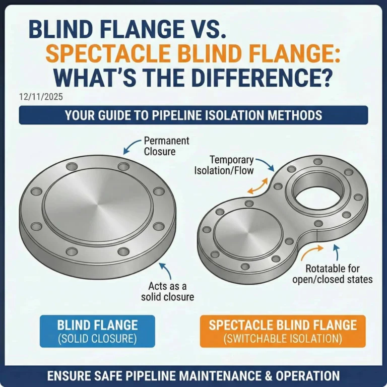
Isolation & Maintenance (Shutdowns): To temporarily seal a line (acting as a “Spade” or “Paddle Blind” per ASME B16.48) while maintenance is performed upstream. Unlike a valve, a blind flange provides a positive, visible, 100% secure shut-off.
Pressure Testing (Hydro-Testing): Used as a robust, high-pressure end cap when performing hydrostatic pressure tests to verify the integrity of a new piping system.
Future Expansion: To cover a valve or vessel nozzle that is reserved for future system expansion, allowing easy bolt-on access when needed without cutting or welding.
Vessel & Manway Covers: Used as high-pressure covers for manways, handholes, or inspection ports on pressure vessels.
Blind Flange Installation Best Practices (Non-Welded)
A blind flange’s integrity depends 100% on the quality of the bolting and gasket installation. A failed seal can be catastrophic. Follow these professional steps to ensure a leak-free joint, especially when working with stainless steel.
1. Gasket Selection
The gasket is the primary sealing element. It MUST be selected to match the flange face (e.g., RF), pressure class, and process fluid. For high-pressure Raised Face (RF) stainless steel systems, a Spiral Wound Gasket (e.g., SS316 winding with a flexible graphite filler) is the industry standard.
2. Alignment
The blind flange face must be perfectly parallel to the connecting flange face. Any misalignment will cause uneven gasket compression and create a leak path.
3. Bolting & Lubrication (CRITICAL Step for Stainless Steel)
WARNING: Preventing Stainless Steel Galling (Seizing)
This is the most common and critical failure point when assembling stainless components. “Galling” (or cold-welding) is when the high-friction, protective oxide layers on stainless steel threads and faces seize under pressure. It can happen with just hand-tightening and can permanently weld the nut to the bolt, forcing you to cut them off.
Anti-Seize is MANDATORY: To prevent galling, you must apply a high-quality, stainless-steel compatible anti-seize lubricant (e.g., nickel-based or ceramic-based) to all bolt threads and nut faces.
This lubricant acts as a physical barrier, reduces friction, and allows the bolt to achieve the correct tension (bolt load) from the applied torque.
4. Tightening Sequence (ASME Star Pattern)
NEVER tighten adjacent bolts. This will warp the flange and guarantee a leak.
Step 1 (30% Torque): Tighten all bolts in a “star pattern” (crisscross, e.g., 1-5-3-7…) to 30% of the final target torque.
Step 2 (60% Torque): Repeat the star pattern, tightening all bolts to 60% of the final target torque.
Step 3 (100% Torque): Repeat the star pattern, tightening all bolts to 100% of the final target torque.
Final Pass: Perform one final pass, tightening each bolt sequentially (e.g., 1-2-3-4…) to 100% torque to ensure all fasteners are at their final tension.

FAQ
Why do Blind Flanges also require a Raised Face (RF)?
Blind flanges require a Raised Face (RF) to concentrate the bolt load onto a smaller surface area, thereby increasing the seating stress on the gasket. According to the formula P = F / A, reducing the contact area (A) significantly increases the sealing pressure (P) for a given bolt force.
This design is critical for high-pressure applications (Class 150 to Class 2500) because:
It allows the gasket to deform and fill microscopic surface irregularities.
It provides better resistance to gasket blowout under system pressure compared to Flat Face (FF) designs.
It ensures seal integrity even if the blind flange center deflects slightly under load.
What is the difference between a Blind Flange and a Pipe Cap?
The primary difference between a Blind Flange and a Pipe Cap is their connection method and accessibility. A Blind Flange is bolted to a pipe end and is designed to be removable for future maintenance or expansion (governed by ASME B16.5). In contrast, a Pipe Cap is typically welded permanently onto the pipe (governed by ASME B16.9), effectively creating a “dead end” that requires cutting to remove.
| Feature | Blind Flange | Pipe Cap |
| Connection | Bolted (Removable) | Welded (Permanent) |
| Standard | ASME B16.5 | ASME B16.9 |
| Primary Use | Access points, cleanouts, future expansion | Permanent pipe termination |
| Seal Type | Gasket compression | Butt-weld fusion |