Butt Weld Stub End Manufacturer | Lap Joint Stub End | Long / Short Pattern | For Lap Joint Flange Assemblies
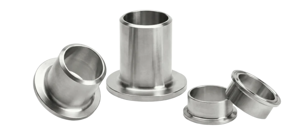
SUNHY supplies butt weld stub ends (also called lap joint stub ends) used with lap joint flanges to build service-friendly piping connections. The flange can rotate freely for easy bolt alignment, while the wetted material is the stub end, making this assembly a practical choice for corrosive or frequently maintained lines.
We offer long pattern and short pattern stub ends, multiple sizes and schedules, consistent weld-end preparation, and project-ready documentation for QA and site acceptance.
- Secure tie-in, consistent fit-up
- Butt weld ready, no piping gaps
- Simplified spool assembly, stable ends
- Concentric & eccentric options
- Heat-traceable marking for QA/QC
- Docs available, per project spec
SUNHY stub ends are produced for consistent lap dimensions, weld-end preparation, and reliable fit-up with lap joint flanges. Select pattern (long/short), schedule, and material grade based on your piping spec and service conditions.
Specification & Standard
Nominal Diameter (DN)
DN 15 – DN 600 (NPS 1/2″ – 24″); larger sizes on request
Product
Butt Weld Stub End / Lap Joint Stub End
End Preparation
Butt weld bevel (per project WPS)
Standards
ASME B16.9 / MSS SP-43 (light-wall stainless, when required) / EN 10253 / GB/T 12459 (per project spec)
Pattern
Long Pattern / Short Pattern (as specified)
Wall Thickness (Schedule)
Sch10 / Sch 40 / Sch 80 / STD / XS / customized thickness
Materials
Stainless (304/316L common) and carbon steel/alloy options on request
Documentation & Inspection
MTC (EN 10204 3.1), dimensional inspection; PMI for stainless upon request; NDT as specified
Butt Weld Stub Ends | Lap Joint Stub End for Lap Joint Flanges
SUNHY supplies butt weld stub ends (also known as lap joint stub ends) designed for lap joint flange assemblies. A stub end is welded to the pipe, and a loose lap joint flange rotates around the stub end for easier bolt alignment and faster maintenance.
This configuration is widely used when you need frequent disassembly, improved installation efficiency, or when you want the wetted material to be corrosion-resistant while keeping the backing flange cost-effective. We offer long pattern and short pattern stub ends in multiple sizes and schedules with consistent weld-end preparation and traceable documentation.
Key Advantages
- Easy Alignment — Rotating flange simplifies bolt-hole alignment during installation.
- Maintenance-Friendly — Faster disassembly for cleaning, inspection, and equipment replacement.
- Wetted Material Control — Process media contacts the stub end, supporting corrosion-control strategies.
- Pattern Options — Long/short pattern choices to match project drawings and flange assemblies.
- QA & Traceability — MTC (EN 10204 3.1), heat number traceability, and inspection options available.
Technical Summary
| ITEM | SPECIFICATION |
|---|---|
| Product | Butt Weld Stub End / Lap Joint Stub End |
| Use With | Lap Joint Flange (loose backing flange) + gasket + bolts |
| Pattern | Long Pattern / Short Pattern (as specified) |
| Nominal Size | DN 15 – DN 600 (NPS 1/2" – 24"); larger sizes available by request |
| Wall Thickness | Sch 10 / Sch 40 / Sch 80 / STD / XS (customized thickness available) |
| End Preparation | Beveled ends for butt welding (per project WPS) |
| Documentation | MTC (EN 10204 3.1), dimensional inspection; PMI/NDT available on request |
Stub End Dimensions | Long Pattern vs Short Pattern | Ordering Guide
Stub ends are typically specified by NPS/DN, schedule (wall thickness), and pattern (long or short). The key checks include the weld-end match to pipe, the lap geometry that supports the backing flange, and the overall length per the applicable standard or project drawing.
What Engineers Typically Confirm
- Pipe size match (NPS/DN) and schedule match to the pipe
- Pattern: Long pattern vs short pattern (per BOM/drawing)
- Lap (flange backing) dimensions to ensure correct flange fit
- Overall length and weld-end bevel per project requirement
Quick Selection Guide
| Item | Long Pattern Stub End | Short Pattern Stub End |
|---|---|---|
| Typical Use | Common choice for general lap joint flange assemblies | When shorter face-to-face is required by design |
| What to Match | Pipe size + schedule + flange compatibility | Pipe size + schedule + flange compatibility |
| Notes | Confirm standard/drawing length and lap dimensions | Confirm standard/drawing length and lap dimensions |
Need a BOM-ready dimensional sheet? Send your NPS/DN + schedule + pattern and the flange type, and we’ll confirm the suitable stub end configuration for your assembly.
Product Assembly | How to Install a Lap Joint Stub End
A lap joint stub end is welded to the pipe, and the lap joint flange (loose backing flange) rotates around the stub end for easier bolt alignment. Proper fit-up, orientation, and qualified welding are critical for long-term sealing performance.
Recommended Assembly Steps
- Slide the lap joint flange onto the pipe first — This is a common field mistake; the flange must be on the pipe before welding the stub end.
- Verify stub end details — Confirm NPS/DN, schedule, and pattern (long/short) match the BOM/drawing.
- Check weld-end bevel & cleanliness — Remove oil/paint/oxidation; keep ends clean and dry.
- Fit-up & tack — Align centerlines, control root gap, tack evenly to reduce distortion.
- Weld per qualified WPS — Follow project welding procedure and heat input requirements (especially for stainless service).
- Assemble the flange joint — Position gasket, align bolt holes easily using the rotating flange, then torque bolts per procedure.
- Inspect & document — Visual/dimensional checks; PMI/NDT if specified; complete documentation for handover if required.
Tip: If the system requires frequent disassembly, keep gasket selection and bolt torque procedures consistent with your project spec to maintain repeatable sealing performance.
Related Products
Butt Weld Tee (Equal / Reducing)
For branch connections in welded piping spools.
Concentric Reducer
Smooth centerline transition for vertical lines and pumps.
Eccentric Reducer
Flat side design to reduce air pockets in horizontal piping.
Butt Weld End Cap
Clean closure for pipe ends—ideal for test spools and headers.
Stub End (Lap Joint)
Common with lap joint flanges for frequent disassembly service.
FAQ
What is a stub end used for?
A Stub End is a butt-weld fitting used in conjunction with a Lap Joint Flange to facilitate easy bolt hole alignment and reduce material costs in piping systems. The stub end is welded to the pipe and serves as the sealing face, while the backing flange remains loose, allowing it to rotate freely for quick alignment during installation. This design allows the use of expensive corrosion-resistant alloys for the wetted stub end while using economical carbon steel for the non-wetted backing flange.
What’s the difference between a stub end and a lap joint flange?
While they work together as a pair, the Stub End acts as the sealing face, whereas the Lap Joint Flange provides the clamping force.
| Feature | Stub End | Lap Joint Flange |
| Primary Function | Provides the gasket sealing surface (Wetted Part).1
| Applies bolting pressure (Non-Wetted Part).4
|
| Installation | Butt-Welded directly to the pipe end.2
| Slides over the pipe; sits loosely behind the stub.5
|
| Movement | Fixed permanently once welded.4
| Rotates freely to align bolt holes.1
|
| Material | Must match the pipe (e.g., Stainless Steel).6
| Can be lower grade (e.g., Carbon Steel).1
|
Long pattern vs short pattern stub end — how do I choose?
The choice between Long Pattern and Short Pattern stub ends depends on your system’s pressure class, space constraints, and design standard.
Choose Long Pattern (ASA/ASME B16.9): Best for high-pressure industrial systems or standard schedule piping (e.g., Schedule 40). The extra length ensures the backing flange does not obstruct the weld, making it safer for critical applications requiring radiographic inspection.
Choose Short Pattern (MSS SP-43): Best for low-pressure, light-wall piping (Schedule 5S or 10S) where space is tight. It is the economic choice for stainless steel systems in industries like water treatment or food processing, offering significant material cost savings.
Do stub ends need to match the pipe schedule?
Yes. The Stub End must match the pipe schedule (wall thickness) of the connecting piping system. Because the stub end is a butt-weld fitting, the Inside Diameter (ID) must align perfectly with the pipe’s ID. Mismatched schedules create an internal “step” or uneven transition, which causes fluid turbulence, increased pressure drop, and potential erosion-corrosion points at the weld joint. Always specify the schedule (e.g., Sch 40S, Sch 10S) to ensure a smooth, laminar flow transition.
What documents can you provide for stub ends?
We provide a complete traceability package to verify compliance with international engineering standards.
Mill Test Reports (MTR): Certified per EN 10204 3.1, detailing the chemical composition and mechanical properties mapped to the specific Heat Number.
NACE Compliance: Certification to NACE MR0175 / ISO 15156 for sour service applications (H₂S environments), ensuring hardness levels are controlled to prevent sulfide stress cracking.
Heat Treatment Charts: Verification of solution annealing for stainless steel and alloy fittings.
PMI Reports: Positive Material Identification testing for alloy grade verification.