








Техническое руководство по кислородному датчику
Сравните расположение, функцию, данные сканирования и требования к покупке датчика кислорода до и после катализатора, не путая Датчик 1 и Датчик 2.
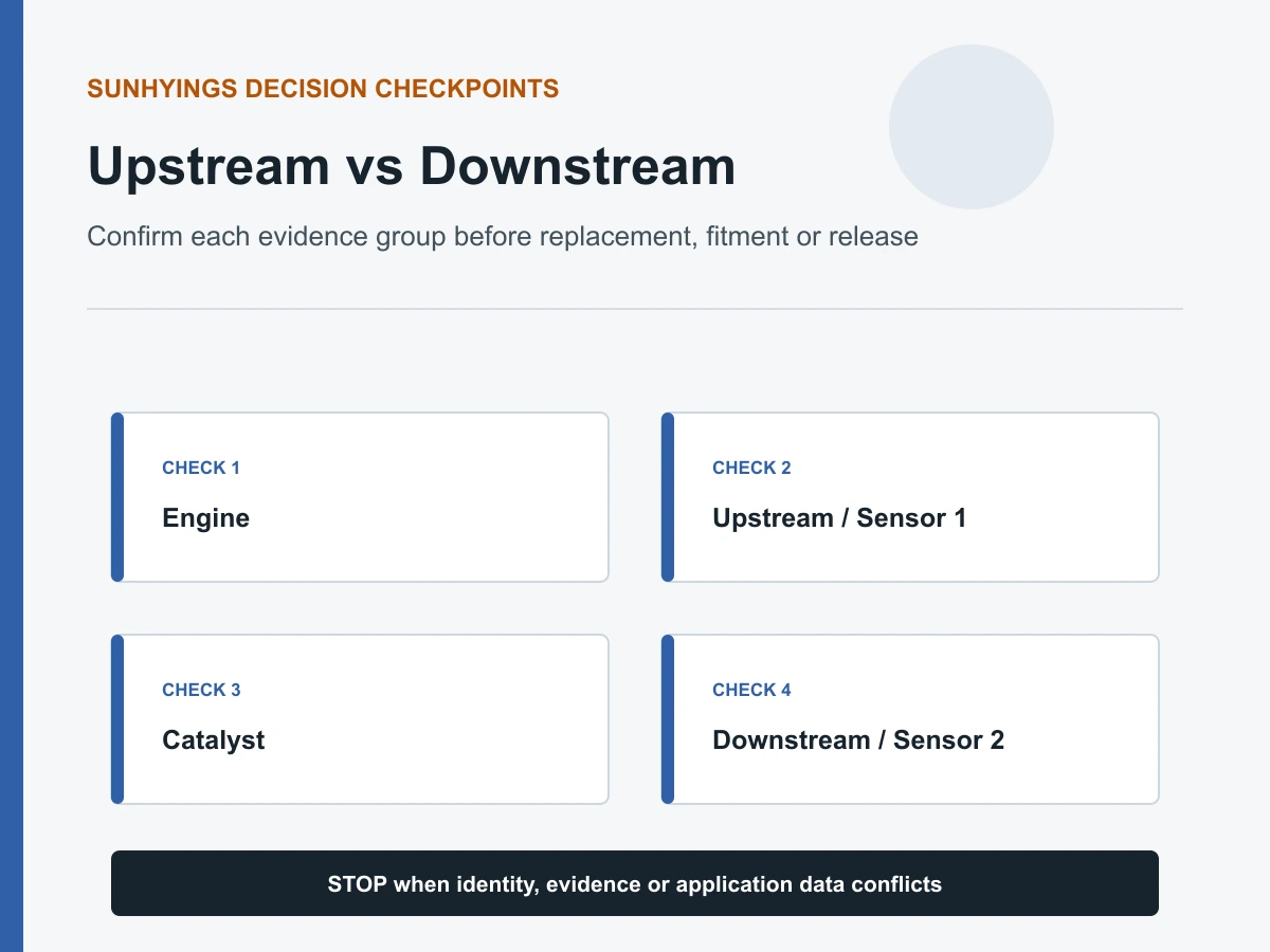
Быстрый ответ
Верхний по потоку кислородный датчик устанавливается перед каталитическим нейтрализатором и обычно используется для обратной связи по топливной смеси. Нижний по потоку датчик устанавливается после нейтрализатора и обычно используется для контроля катализатора. Верхний по потоку обычно означает Датчик 1, а нижний — Датчик 2, но точный ряд, позиция и деталь должны быть подтверждены по данным обслуживания или совместимости автомобиля.
Взгляд на верхнее и нижнее течение
| Вопрос | Верхний по потоку датчик | Датчик нижнего потока |
|---|---|---|
| Типичное расположение | Перед каталитическим нейтрализатором | После каталитического нейтрализатора |
| Общее название положения | Датчик 1 / до катализатора / передний | Датчик 2 / после катализатора / задний |
| Основная стратегия | Управление смесью и топливом с обратной связью | Обратная связь монитора катализатора |
| Ожидаемые данные | Сильно зависит от технологии узкополосного или широкополосного датчика | Часто стабильнее переднего датчика при работающем катализаторе, но стратегия автомобиля варьируется |
| Риск при покупке | Неверная калибровка, разъем или ряд | Неверная длина кабеля, трассировка, разъем или положение |
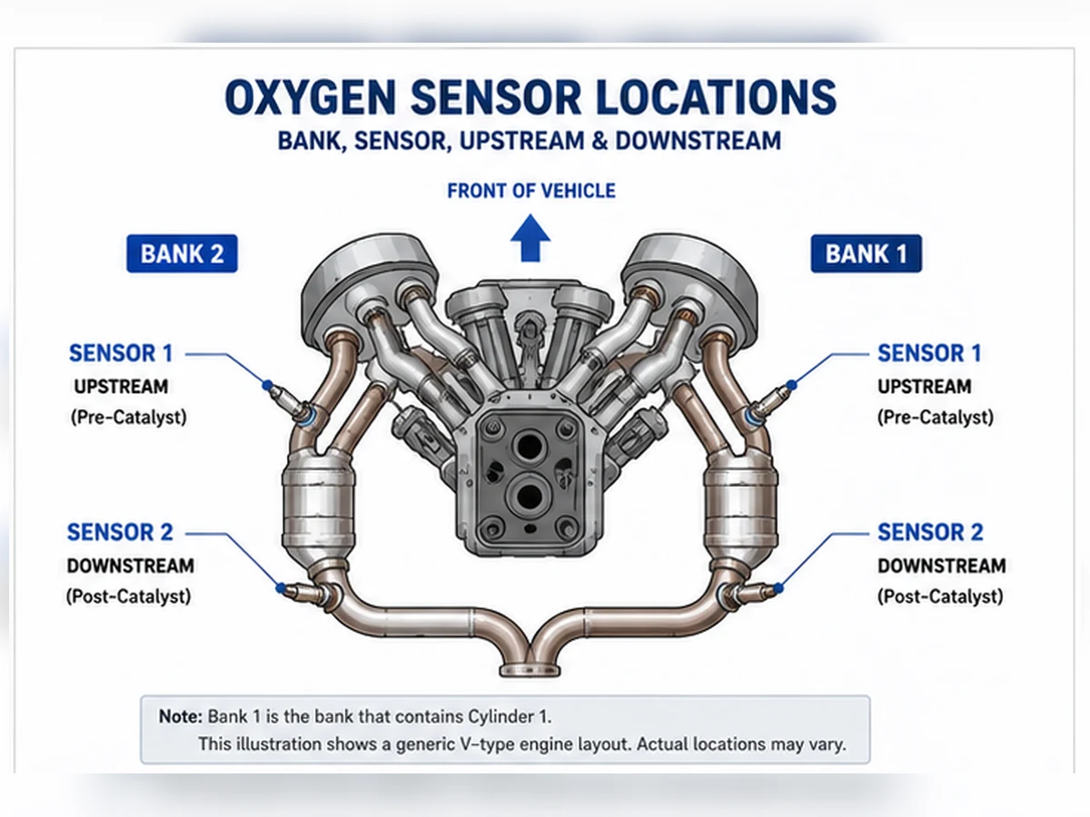
Наименование переднего, заднего, банка и датчика
“Передний” и “задний” могут быть неоднозначными на поперечных двигателях или системах с несколькими катализаторами. Используйте идентификацию ряда и датчика, где это возможно. Ряд 1 содержит цилиндр 1. Датчик 1 — это датчик до катализатора для этого ряда; датчик 2 — после. На некоторых автомобилях могут быть дополнительные датчики или другая терминология, поэтому руководствуйтесь сервисной информацией.
Почему данные сканирования должны выглядеть иначе
Обычный узкополосный датчик до катализатора может переключаться между богатой и бедной смесью во время работы в замкнутом контуре. Широкополосный датчик отображается иначе и может быть представлен как ток, лямбда или заданная эквивалентность. Сигнал после катализатора интерпретируется в зависимости от работы катализатора. Сравнение двух графиков без предварительного определения технологии и условий работы может привести к ложному диагнозу.
Коды, упоминающие положение
Код, указывающий на конкретную позицию, сужает круг проверяемой цепи, но не доказывает, что чувствительный элемент неисправен. Проверьте разъем и жгут проводов, питание и заземление нагревателя, утечку выхлопных газов и рабочие данные. Коды P0420 или P0430 не следует рассматривать как указание на замену датчика после катализатора.
Можно ли взаимозаменять датчики верхнего и нижнего течения?
Не предполагайте взаимозаменяемость. Два датчика могут иметь одинаковый размер резьбы или внешний вид разъема, но отличаться технологией, калибровкой, длиной кабеля, защитным экраном или ключом разъема. Сверяйтесь с эталоном OE и точным автомобилем, двигателем, рынком/пакетом выбросов, рядом и позицией.
Контрольный список проверки положения
- Прочитайте полное описание кода и данные стоп-кадра.
- Определите цилиндр 1 и ряд 1 по сервисной информации.
- Проследите поток выхлопных газов, чтобы различить положения до и после катализатора.
- Сравните разъем, длину кабеля и клипсы для фиксации жгута.
- Перед заказом подтвердите эталонный номер OE и технологию датчика.
Идентификация положения предшествует интерпретации сигнала
Термины «до» и «после» описывают расположение относительно катализатора, а не универсальное физическое направление на автомобиле. На двухрядном двигателе каждый ряд может иметь свой датчик 1 и датчик 2. Некоторые выпускные системы добавляют дополнительные катализаторы или датчики. Перед проверкой подтвердите нумерацию цилиндров, проследите путь выхлопа и сопоставьте код или идентификатор данных с физическим разъемом.
| Ввод идентификатора | Решение по датчику до катализатора | Решение по датчику после катализатора |
|---|---|---|
| Цилиндр и ряд | Найдите датчик 1 на ряду, содержащем указанные цилиндры | Найдите датчик 2 после контролируемого катализатора этого ряда |
| Поток выхлопных газов | Перед соответствующим катализатором | После соответствующего катализатора |
| Каталожные данные | Необходимо указать точный банк/положение и технологию | Необходимо указать точное положение, маршрут проводки и разъем |
| Схема обслуживания | Подтверждает физический разъем и маршрут жгута | Предотвращает путаницу с дополнительными датчиками после катализатора |
Как различаются их роли управления
Обратная связь по потоку до катализатора
После выполнения условий активации блок управления использует обратную связь по потоку до катализатора с учетом расхода воздуха, нагрузки, температуры и других параметров для оценки смеси. Узкополосный датчик может переключаться вокруг своей контрольной точки, в то время как широкополосный датчик может быть представлен как ток, лямбда или коэффициент избытка воздуха. Показание обедненной смеси может быть точным свидетельством неучтенного воздуха или низкой подачи топлива, а не неисправности датчика.
Мониторинг потока после катализатора
Нижний по потоку датчик обычно помогает блоку управления оценивать поведение катализатора по накоплению кислорода. Его сигнал интерпретируется относительно сигнала верхнего датчика и заданных условий мониторинга. Задний датчик не должен просто показывать одно фиксированное напряжение, и код катализатора не доказывает, что задний датчик нужно заменять.
Исключения из стратегии
Производители могут использовать информацию с нижнего датчика для дополнительных адаптаций или диагностики. Общие роли дают ориентировку, а не разрешение обобщать логику одного автомобиля на другой. Используйте точную сервисную информацию для конкретного автомобиля, двигателя, пакета выбросов и калибровки.
Сравнивайте сигналы только при допустимых условиях
| Состояние | Наблюдение верхнего датчика | Наблюдение нижнего датчика | Ограничение |
|---|---|---|---|
| Холодный пуск | Может еще не обеспечивать замкнутую обратную связь | Монитор катализатора обычно не готов | Температурные критерии и критерии включения не выполнены |
| Устойчивая работа в прогретом состоянии | Смесевая реакция, специфичная для технологии | Оценено по поведению катализатора | Утечки и неисправности топливной системы могут исказить оба параметра |
| Ускорение | Команда обогащения может изменить сигнал | Реакция может быть задержана накоплением в катализаторе | Не сравнение установившегося режима |
| Отсечка топлива при замедлении | Возможно высокое содержание кислорода в выхлопе | Реакция зависит от катализатора и стратегии | Не маркируйте ожидаемое поведение как неисправность |
Используйте позиционно-зависимые коды в качестве тестовых путей
Коды цепи датчика 1 или коды реакции
Проверьте указанный ряд и цепь до датчика, но также оцените реальные условия смеси. Проверьте целостность разъема, работу нагревателя, опорное или сигнальное заземление, утечки выхлопа перед датчиком и коррекции топлива. Тест реакции должен соответствовать технологии узкополосного или широкополосного датчика.
Коды цепи датчика 2 или коды нагревателя
Проверьте разъем и жгут после катализатора, которые могут подвергаться воздействию тепла, воды и ударов снизу автомобиля. Проверьте цепи питания, управления и сигнала в соответствии с указаниями. Не заменяйте диагностику эффективности катализатора прямым тестом цепи.
P0420 и P0430
Эти коды касаются эффективности каталитической системы. Убедитесь, что нет активного пропуска зажигания, неисправности смеси или утечки выхлопа, проверьте оба сигнала датчиков и выполните процедуру проверки катализатора. Замена нижнего датчика оправдана только в том случае, если его собственные показания свидетельствуют о невозможности корректной передачи данных.
Почему совпадающая резьба не делает позиции взаимозаменяемыми
Верхний и нижний датчики могут различаться по технологии измерения, калибровке, характеристикам нагревателя, защитному экрану, назначению контактов разъема, длине кабеля и клипсам. Даже если одна деталь физически вкручивается в оба отверстия, блок управления может ожидать другую электрическую систему. Не удлиняйте, не прилагайте усилий и не обрезайте жгут проводов прямого подключения, чтобы дотянуться до неправильного положения.
| Сравнительный элемент | Требуются доказательства | Отклонять, когда |
|---|---|---|
| Ссылка OE | Текущая запись применения для точного положения | Перекрестная ссылка не проверена или относится к другому варианту выбросов |
| Технология | Узкополосный, широкополосный/A/F или заданная конструкция | Список основан только на количестве проводов |
| Разъем | Ключ, защелка и назначение цепи | Корпус принудительно установлен или контакты отличаются |
| Провод и клипсы | Правильная длина и термобезопасная прокладка | Кабель не должен быть натянут или оставлен рядом с движущимися/горячими деталями |
Составной сценарий: задний код диагностируется на переднем разъеме
Составной инженерный сценарий: техник следует общей маркировке “задний датчик” на поперечном двигателе и проверяет не тот разъем. Схема выпускной системы показывает, что разъем датчика Bank 1 Sensor 2 проложен к другой стороне моторного отсека. Правильная идентификация положения меняет результат проверки цепи и предотвращает замену исправного датчика. Это составной учебный сценарий, а не реальный случай клиента Sunhyings.
Запишите позицию перед заказом
Зафиксируйте полное описание кода, идентификацию двигателя, рынок/пакет по выбросам, расположение цилиндра 1, ряд, номер датчика, отношение к катализатору, номер OE, форму разъема и трассу кабеля. Фото должно показывать контекст, а также сам разъем. Эта запись позволяет продавцу или ремонтнику проверить точное положение, не превращая “передний” или “задний” в заявление о совместимости.
Проверьте ремонт без принудительного заключения
После ремонта цепи, датчика, выпускной системы или двигателя сначала проверьте физическую установку. Убедитесь, что правильный разъем зафиксирован, кабель закреплен вдали от тепла и движения, и отсутствует утечка выхлопа. Затем наблюдайте правильный идентификатор данных upstream или downstream при рабочих условиях, указанных производителем. Сигналы следует интерпретировать вместе с топливными коррекциями, командным состоянием и статусом монитора.
Форма сигнала downstream, которая становится более стабильной, сама по себе не является доказательством исправности катализатора, так же как изменение формы сигнала upstream не является доказательством правильной калибровки датчика. Монитор должен работать в допустимых условиях, и исходная неисправность не должна возвращаться. Постоянные коды могут оставаться до тех пор, пока модуль не зафиксирует прохождение монитора; многократная очистка памяти может задержать, а не ускорить подтверждение.
Когда оба положения показывают необычные данные
Когда показания до и после катализатора аномальны, ищите причины, влияющие на весь выпускной тракт: пропуски зажигания, неправильная подача топлива, утечка выхлопа, проблемы с температурой или неподдерживаемые параметры сканера. Замена обоих датчиков может удалить полезные улики и оставить общую первопричину.
Когда только в одном положении электрическая неисправность
Неисправность обрыва, короткого замыкания или нагревателя в конкретном положении следует искать по правильной схеме проводки. Проверьте общие цепи питания, не предполагая, что каждый датчик использует один и тот же предохранитель или массу. Нагрузите подозрительные цепи и проверьте контакты. Код, указывающий на один датчик, не доказывает, что заменяемый элемент является точкой отказа.
Вверх и вниз по потоку при типовых схемах выпуска
До катализатора означает перед контролируемым катализатором; после катализатора — после него. Эти слова не гарантируют, что датчик физически находится спереди или сзади автомобиля. Компоновка может разместить датчик перед катализатором позади двигателя, а в некоторых системах используются близко расположенные катализаторы плюс дополнительные поддонные катализаторы. Проследите поток выхлопа и используйте точную сервисную информацию.
| Компоновка | Типичное расположение до катализатора | Типичное расположение после катализатора | Риск неправильной идентификации |
|---|---|---|---|
| Рядный двигатель, один контролируемый катализатор | Датчик 1 до катализатора | Датчик 2 после катализатора | Дополнительные датчики или ступени катализатора могут изменить количество |
| V-образный двигатель, отдельные катализаторы на каждом ряду | B1S1 и B2S1 до катализаторов своих рядов | B1S2 и B2S2 после катализаторов своих рядов | Ряд 1 определяется цилиндром 1, а не универсальной стороной |
| Близкорасположенный плюс подпольный катализатор | Датчик перед соответствующим контролируемым катализатором | Один или несколько датчиков могут следовать за разными стадиями катализатора | “Задний” может не однозначно идентифицировать датчик 2 или датчик 3 |
| Одиночный выпуск после слияния двух рядов | Датчики, специфичные для ряда, могут быть выше по потоку от места слияния | Общий датчик ниже по потоку может контролировать объединенный путь | Наименование рядов и количество физических труб не всегда совпадают с интуицией |
| Поперечный двигатель с компактной компоновкой | Может быть обращен к моторному щиту или радиатору в зависимости от расположения цилиндров/выпускного коллектора | Может находиться ниже катализатора или под днищем | Сокращения «водитель/пассажир» и «передний/задний» могут быть неверными |
Роль управления: обратная связь по смеси против контроля катализатора
Верхний по потоку датчик обычно обеспечивает быструю обратную связь по смеси после выполнения условий замкнутого цикла. Нижний по потоку датчик обычно участвует в мониторинге накопления кислорода в катализаторе. Это основные роли, а не универсальное разрешение игнорировать стратегию обслуживания. Некоторые системы управления используют информацию от нижнего датчика для адаптации или дополнительной диагностики.
| Точка принятия решения | Верхний / до нейтрализатора | Нижний / после нейтрализатора |
|---|---|---|
| Основной вопрос | Что показывает датчик кислорода в отношении обратной связи по смеси? | Как ведет себя газ после катализатора в условиях мониторинга? |
| Общепринятая технология | Узкополосный или широкополосный/A/F в зависимости от применения | Часто узкополосные, но решающим является подтверждение применения |
| Ожидаемая реакция | Технологически специфичны и обычно реагируют на изменения смеси | Интерпретируются с учетом хранения катализатора и поведения выше по потоку |
| Основные искажающие факторы | Неисправности впуска/топлива/зажигания, утечка до датчика, цепь и температура | Неисправности выше по потоку, состояние катализатора, утечки, смесь, цепь и состояние монитора |
| Ошибка замены | Заказ по “фронту” без банка/технологии | Замена из-за наличия P0420/P0430 |
Интерпретация сигнала меняется в зависимости от технологии и режима работы
Теплый циркониевый узкополосный датчик перед катализатором может переключаться вокруг своей контрольной точки во время коррекции замкнутого контура. Широкополосный датчик/датчик A/F может отображаться как ток накачки, лямбда, коэффициент избытка воздуха или производное значение производителя. Их не следует оценивать по одному и тому же шаблону напряжения. Сигнал заднего узкополосного датчика формируется накоплением кислорода в катализаторе и стратегией мониторинга, поэтому миф о фиксированном напряжении также небезопасен.
| Рабочее состояние | Наблюдение верхнего датчика | Наблюдение нижнего датчика | Граница интерпретации |
|---|---|---|---|
| Холодный пуск | Может еще не обеспечивать активную обратную связь | Монитор катализатора обычно не готов | Условия включения нагревателя и температуры имеют значение |
| Теплый холостой ход | Обратная связь по смеси может быть активной | Низкий расход и небольшие утечки могут влиять на показания | Холостой ход сам по себе не является полной проверкой системы |
| Устойчивый режим | Коррекция топлива и реакция могут быть оценены | Сравнение катализатора может быть значимым при включении | Скорость, нагрузка и температура должны быть стабильными |
| Ускорение | Команда обогащения может изменить сигнал | Реакция может быть задержана накоплением в катализаторе | Не является сравнением катализатора в установившемся режиме |
| Отсечка топлива при замедлении | Можно ожидать высокое содержание кислорода в выхлопе | Поведение зависит от хранения и стратегии | Ожидаемое событие не должно помечаться как неисправность |
Диагностическая карта для конкретного положения
| Проблема | Акцент на тестировании выше по потоку | Акцент на тестировании ниже по потоку | Общие проверки |
|---|---|---|---|
| Низкий/высокий сигнал | Фактическая смесь, коррекции топлива и опорная цепь | Цепь сигнала, утечки и контекст после катализатора | Разъем, технология и точное положение |
| Медленный отклик | Допустимая спецификация стимула и реакции обедненной/обогащенной смеси | Процедура мониторинга и влияние катализатора | Пределы температуры, загрязнения и данных сканирования |
| Код нагревателя | Защищенное питание/управление и трасса жгута до катализатора | Прокладка жгута под днищем и общее питание | Нагруженное тестирование, контакты и заданные сопротивление/ток |
| P0420/P0430 | Контроль смеси и исправность переднего датчика | Исправность заднего датчика на пути катализатора | Пропуски зажигания, утечки, загрязнение и процедура проверки катализатора |
| Плохой расход топлива | Возможное прямое влияние через смещенную обратную связь | Обычно не первый подозреваемый в системе управления топливом | Подтвердите фактическое использование топлива и конкурирующие причины |
Почему детали до и после катализатора могут выглядеть одинаково, но остаются невзаимозаменяемыми
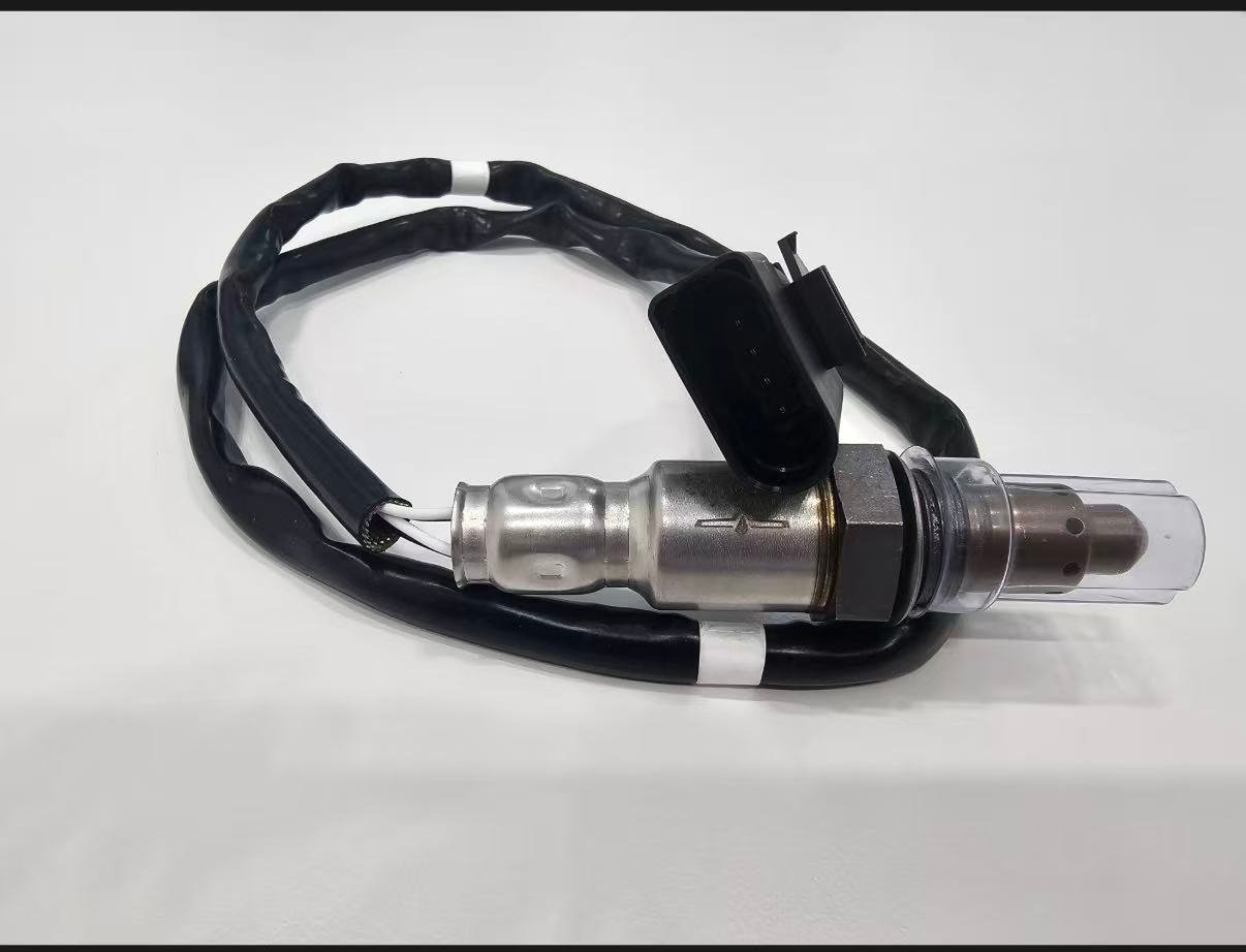
Два датчика могут иметь одинаковую резьбу и даже похожий корпус, но отличаться технологией измерения, калибровкой, нагревателем, ориентацией разъема, назначением выводов, длиной кабеля, зажимами и экраном. Более длинный кабель не является автоматически безопасной заменой; нефиксированный кабель может касаться выхлопных или движущихся частей. Более короткий кабель ни в коем случае нельзя растягивать или удлинять, чтобы дотянуться до неправильного положения.
| Идентификационный признак | Требуются доказательства | Небезопасное сокращение |
|---|---|---|
| Сопоставление OE/применения | Актуальный источник для точного автомобиля, двигателя и позиции | Одна перекрестная ссылка скопирована без изменений |
| Технология | Спецификация продукта и автомобиля | Подсчет проводов |
| Разъем/распиновка | Ключ, штифты, расположение клемм и схема | Цвет разъема или принудительная посадка |
| Провод и клипсы | Длина и утвержденный маршрут для точного положения | Удлинение, обрезка или связывание излишков вблизи источника тепла |
| Экран/резьба | Чертеж или проверенная физическая спецификация | Предположение, что общая резьба обеспечивает взаимозаменяемость |
Сложный случай: два похожих разъема были установлены в неправильные положения
Сценарий составной мастерской: После работ по выпускной системе автомобиль устанавливает коды неисправностей, зависящие от положения. Оба датчика присутствуют, и их разъемы можно проложить к ближайшим ответвлениям. Техник сверяет цвета проводов, идентификаторы разъемов и служебную маршрутизацию и обнаруживает, что разъемы перепутаны. Восстановление правильного соответствия физического и логического подключения устраняет конфликт без замены датчиков.
Сценарий показывает, почему метки сканирования, физическое положение и маршрут разъема должны совпадать до интерпретации данных. Это составной шаблон, а не ремонт клиента Sunhyings.
Сложный случай: датчик после катализатора не был автоматическим ответом на P0420
Составной диагностический сценарий: Появляется активный график заднего датчика и сохранен код катализатора. Перед заказом заднего датчика мастерская обнаруживает утечку выхлопа перед ним и аномальную коррекцию топлива вверх по потоку. Утечка и неисправность смеси устранены, точные датчики проверены, и монитор катализатора запущен повторно. Решение о детали откладывается до тех пор, пока система не будет протестирована в допустимых условиях.
Это не гарантирует, что устранение утечки исправит любой код катализатора. Это показывает порядок доказательств, необходимый перед тем, как осудить датчик ниже по потоку или катализатор.
Запись заказа для конкретного положения
- VIN/YMME, двигатель и конфигурация рынка/выбросов
- Источник цилиндра 1, идентификация ряда и полный номер датчика
- Положение относительно точного контролируемого катализатора
- Ссылка OE и контролируемая ревизия перекрестных ссылок
- Узкополосная, титановая или широкополосная/A/F технология
- Поверхность разъема, ключ, контакты, длина провода, зажимы, резьба и экран
- Диагностическое обоснование для замены данного компонента
Разработайте тест ответа, отвечающий на вопрос, специфичный для должности
Перед проверкой сформулируйте вопрос. Для датчика до катализатора это может быть соответствие регистрируемой смеси контролируемому изменению «богатая/бедная» в пределах спецификации автомобиля. Для датчика после катализатора это может быть проверка отклика цепи и правдоподобность его поведения во время заданного мониторинга катализатора. Стимул, ожидаемый параметр, временной масштаб и пределы допуска должны соответствовать технологии датчика и сервисной информации.
| Поле разработки теста | Пример для датчика до катализатора | Пример для датчика после катализатора | Недопустимый ярлык |
|---|---|---|---|
| Эксплуатационные условия | Прогретый замкнутый контур при заданных оборотах/нагрузке | Условия включения мониторинга катализатора | Снимок холодного холостого хода |
| Канал данных | Корректный элемент напряжение/ток/лямбда | Именованный элемент заднего датчика и опорный элемент переднего датчика | Немаркированный общий график |
| Стимул | Утвержденное контролируемое изменение смеси | Монитор производителя или определенная процедура реагирования | Случайное срабатывание дроссельной заслонки |
| Проверки на смешивание | Утечки, давление топлива, поток воздуха и коррекции | Утечки, достоверность до катализатора, пропуски зажигания и состояние катализатора | Предположение, что каждое изменение исходит от датчика |
| Заключение | Пройдено/не пройдено по точным спецификациям | Продолжить путь цепи/датчика/катализатора | “Выглядит медленно” без шкалы или предела |
При использовании диагностического инструмента для получения или фильтрации параметра документируйте инструмент и метку данных. Если автомобиль не поддерживает необходимую информацию, используйте метод OEM, а не изобретайте универсальную замену. Не вносите изменения в топливо или воздух таким образом, чтобы это создавало небезопасную температуру выхлопа или неконтролируемую работу.
Изменение положения влияет на тепловое и трассовое воздействие
Датчики, расположенные выше по потоку, могут видеть более высокую и быстро меняющуюся температуру выхлопа. Датчики, расположенные ниже по потоку, часто имеют более длинные трассы под днищем, подверженные воздействию воды, дорожного мусора и перемещению жгутов. Эти особенности помогают планировать осмотр, но не заменяют чертежи применения. Проверьте тепловые экраны, втулки, зажимы и расположение разъемов для конкретного автомобиля.
| Воздействие | Возможная проблема на входе | Возможная проблема на выходе | Протокол контроля |
|---|---|---|---|
| Нагрев | Близость к коллектору/катализатору и быстрая цикличность | Лучистое тепло выхлопа и отсутствие экранов | Фото полного установленного маршрута и зазоров |
| Вода/мусор | Уплотнение разъёма в моторном отсеке | Воздействие на днище, попадание соли и воды | Состояние уплотнения, клемм и жгута |
| Перемещение | Перемещение двигателя и натяжение проводов | Перемещение выхлопной системы и длинный неподдерживаемый провод | Разгрузка натяжения и расположение каждого хомута |
| Доступ для обслуживания | Ограниченный доступ к коллектору или экрану | Доступ к подъемной/опорной и корродированной пробке | План доступа и состояние резьбы |
Доказательства поставщика должны сохранять идентичность положения
Дистрибьютор не должен объединять восходящее и нисходящее покрытие в одну маркетинговую группу без контролируемых записей на уровне деталей. Каждая продаваемая деталь требует ревизии, привязки к OE/применению, спецификации технологии, разъема и вывода, области проверки, производственного контроля и прослеживаемости. Сертификат системы менеджмента качества может подтверждать проверку технологического процесса только в пределах указанного юридического лица, площадки и области действия; он не доказывает, что конкретная деталь подходит для обеих позиций.
| Запись поставщика | Вопрос позиции, на который она должна ответить | Сигнал отклонения или задержки |
|---|---|---|
| Таблица применения | Какие строки транспортного средства/двигателя/системы выпуска/банка/датчика утверждены? | Список на уровне модели без указания позиции |
| Чертеж изделия | Корректно ли расположение разъема, вывода, зажимов, резьбы и экрана? | Только общее фото семейства |
| Электрические характеристики | Соответствует ли технология/нагреватель/схема стратегии позиционирования? | Количество проводов как доказательство совместимости |
| Отчет о валидации | Какие идентифицированные образцы и условия были протестированы? | Названия тестов без критериев, результатов или идентификации образца |
| Уведомление об изменении | Будут ли критичные для позиционирования изменения конструкции/данных вызывать проверку? | Несанкционированная замена разъема, кабеля или каталога |
Анализ возврата при подозрении на несоответствие выше/ниже по потоку
Сохраните наклейку и партию поставки, точную идентификацию автомобиля, установленное положение, источник карты OE, сравнение старого/нового и результаты диагностики. Жалоба на короткий провод или отличие разъема может указывать на ошибку упаковки, ошибку каталога, неправильное положение или незарегистрированный вариант выбросов. Возвращающийся DTC может вместо этого отражать проблемы с цепью автомобиля или первопричиной. Проверьте как соответствие продукта, так и точность применения.
Не изменяйте жгут проводов прямой установки, чтобы установить спорную деталь. Держите датчик чистым, документируйте поверхность разъема и трассу, и приостановите работу, пока запись о детали и данные автомобиля не совпадут. Это защищает клиента и сохраняет доказательства для корректирующих действий.
Дерево решений выше/ниже по потоку от жалобы до подтвержденного ремонта
- Определите жалобу. Зафиксируйте проблему с управляемостью, расходом топлива, контрольной лампой или проверкой при повторяемых условиях эксплуатации.
- Соберите доказательства системы. Считайте все модули и сохраните статус кодов, стоп-кадр, готовность и связанную информацию о пропусках зажигания или управлении топливом.
- Назовите позицию. Используйте нумерацию цилиндров двигателя и схему выпуска для определения ряда, номера датчика, катализатора и физического разъема.
- Определите технологию. Установите, является ли указанная позиция узкополосной, титановой или широкополосной/А/Т, и выберите поддерживаемые данные и тесты.
- Проверьте цепь и контекст. Проверьте целостность питания/управления нагревателя, сигнала/опорного сигнала, утечки выхлопа, регулировки и причины, связанные с конкурирующими двигателями.
- Выполните корректный тест отклика. Соблюдайте требования к температуре и состоянию управления, документируйте стимул, единицы измерения, временную шкалу и результат.
- Отделите датчик от логики катализатора. При проблемах с задним датчиком или P0420/P0430 подтвердите исправность вышестоящего датчика и следуйте пути катализатора.
- Выберите точную деталь. Соответствие OE/применению, положению, технологии, разъему, выводу, зажимам, резьбе и экрану.
- Устанавливайте без изменения системы выпуска. Соблюдайте инструкции по безопасности, моменту затяжки, обработке резьбы и прокладке; сохраняйте все экраны.
- Проверьте исходный вопрос. Повторно проверьте цепь/отклик и завершите соответствующий юридический монитор в документированных условиях.
Если на каком-либо этапе возникают противоречия в доказательствах, остановите принятие решения о детали и устраните противоречие. Например, если в каталоге указано «ниже по потоку», но маршрут разъема достигает предкаталитического бункера, ни один из источников не должен молчаливо предпочитаться. Проверьте VIN/конфигурацию, редакцию каталога, снятую деталь и сервисную схему и зафиксируйте решение.
Коммерческие претензии, которые данное сравнение не поддерживает
Настоящее руководство не устанавливает, что Sunhyings хранит на складе все датчики до и после катализатора, что одна деталь подходит для всех положений или что замена датчика снизит выбросы или расход топлива на фиксированный процент. Оно не публикует непроверенные номера OE, значения крутящего момента, цены, MOQ, сроки поставки или одобрения. Эти детали требуют индивидуального запроса котировки и проверки доказательств.
Действительным коммерческим предложением является подача контролируемой заявки и запроса на продукт. Покупатели должны указать рынок сбыта, список OE/деталей, данные YMME/двигатель/выбросы и положение, ожидаемое количество, упаковку, требования к валидации и документации. Только подтвержденная информация о проекте должна попадать в коммерческое предложение или на страницу продукта.
Для розничного запроса минимальная полезная заявка меньше, но все же точна: VIN или полные YMME/двигатель, рынок выбросов, положение банка/датчика, читаемый номер старой детали и фотографии разъема/провода. Код неисправности или слова “датчик до катализатора” не могут заменить эти данные о совместимости.
Сохраняйте доказательства вместе с заказом: редакцию каталога, предоставленные данные автомобиля, выбранное положение и сравнительные фотографии. Если доставленный разъем или провод противоречит записи, остановитесь перед установкой и устраните несоответствие. Это безопаснее и полезнее, чем модификация детали прямого монтажа.
Подготовьте запрос на установку или поиск источника
Отправьте номер OE, год/марку/модель, данные о двигателе или VIN, рынок и пакет по выбросам, точное положение банка/датчика, разъем и фотографии старой детали, количество и любые требования к упаковке или одобрению. Sunhyings проверит предоставленные данные на предмет возможности и осуществимости поиска источника; установка не подтверждается до тех пор, пока не будут сопоставлены доказательства применения.
Свяжитесь с Sunhyings для предоставления данных по установке
Часто задаваемые вопросы
Датчик 1 находится до или после?
Датчик 1 обычно находится до каталитического нейтрализатора для своего ряда. Уточните информацию по обслуживанию автомобиля, так как компоновка систем может различаться.
Датчик 2 — это задний кислородный датчик?
Датчик 2 обычно является датчиком после катализатора, но используйте схему ряда и обслуживания, а не полагайтесь только на обозначения «передний» или «задний».
Можно ли использовать датчик выше по потоку в нижнем по потоку?
Только если проверенный каталог или перекрестная ссылка OE указывают точную деталь для обеих позиций. Внешнее сходство не гарантирует взаимозаменяемость.
Управляет ли топливом датчик после себя?
Его основная роль обычно заключается в мониторинге катализатора, хотя стратегии управления различаются. Не обобщайте логику одного автомобиля на все автомобили.
Означает ли код P0420 неисправность нижнего датчика?
Номер P0420 указывает на эффективность системы катализатора. Перед заменой деталей диагностируйте данные датчиков, герметичность выпускной системы и работу катализатора.