")
You need to choose stainless steel flanges that match the design conditions of your piping system—not just the normal operating conditions. In the field, flange selection mistakes usually show up as one of three things: seepage after the first heat-up/cool-down cycle, a failed hydrotest, or recurring leaks after maintenance reassembly.
Picking the right flange affects more than safety and performance:
- It controls installation effort (fit-up, welding/NDE time, bolt-up time) and the risk of rework.
- It reduces corrosion-driven maintenance when the alloy and facing/gasket match the actual media.
- It helps you avoid downtime caused by gasket blowout, bolt relaxation, or crevice corrosion around the joint.
Your choice sets the foundation for a safe and efficient operation.
Define Project Needs for Flange Selection
Before you choose stainless steel flanges, gather the project’s technical requirements in a way that an installer and an inspector can verify. At minimum, capture: design pressure, design temperature, media chemistry (including contaminants), applicable standard (ASME/EN/DIN), facing type, gasket type, and bolting requirements.
Project Pressure and Temperature
Direct Answer:
You must know the maximum design pressure and maximum design temperature your system will face, including credible upsets (thermal excursions, pressure surges, start-up transients).
Pressure class is not a single “psi rating.” Under ASME B16.5, the allowable pressure depends on temperature and the material group. As temperature rises, allowable pressure drops, and the drop is not linear. If your design basis references ASME process piping rules, confirm how your project defines design conditions (commonly aligned with ASME B31.3).
Example (quick reference only): A182 F316 material group ratings show a clear derating trend with temperature. Always verify against the current edition of your purchased standard; this table is a convenience snapshot based on a commonly used quick-reference chart derived from ASME B16.5 material group tables.
| Temperature (°F) | Example Pressure Rating (psig) |
|---|---|
| 100 | 230 |
| 200 | 195 |
| 300 | 175 |
| 400 | 160 |
| 500 | 150 |
Tip:
Flanges are classified by “classes” under ASME B16.5 (e.g., 150, 300, 600). Class selection must be checked at design temperature. If you only check the rating at ambient temperature, you can unknowingly under-rate the joint at operating conditions.
")
Quick Steps for Pressure and Temperature:
- Document design pressure and design temperature (include credible surges and thermal excursions).
- Confirm the governing flange standard (ASME B16.5 / ASME B16.47 / EN/DIN) and material group.
- Verify allowable pressure at design temperature, then select a class with appropriate margin for your project’s rules.
Field Example (leak after heat-up):
A steam-traced chemical line passed a room-temperature hydrotest, then developed seepage after the first heat-up. The root cause was that class selection was checked at ambient instead of design temperature, and bolt load relaxed after thermal cycling. The fix was upgrading the class and reassembling per a controlled bolt-up procedure (patterned tightening, verified lubrication, and re-torque where allowed) using guidance aligned with ASME PCC-1.
Media and Corrosivity

Direct Answer:
You must match the flange alloy and joint details (facing + gasket + bolting) to the actual media, including contaminants like chlorides, sulfides, cleaning chemicals, and oxygen content.
The type of media in your piping drives corrosion risk at the flange joint. Stainless failures at flanges are often local (pitting/crevice at the gasket contact band or under deposits) rather than uniform wall loss. Chloride-bearing services are especially unforgiving: austenitic grades may pit or crevice-corroded in stagnant zones, while duplex grades can offer improved resistance in many chloride applications when properly specified and fabricated.
Engineering evidence point you can use during selection: the pitting resistance equivalent number (PREN) is commonly referenced as a screening indicator (higher generally improves pitting resistance). A widely cited PREN relationship is provided in technical guidance from the Nickel Institute: PREN guidance (Nickel Institute).
| Grade | Composition | Advantages |
|---|---|---|
| 316 / 316L | ~16-18% chromium, ~10-14% nickel, ~2-3% molybdenum | General-purpose corrosion resistance with improved pitting/crevice resistance vs 304 due to Mo; commonly specified for chemical and marine-adjacent service (risk still depends on chloride level, temperature, and stagnation). |
| 2205 (Duplex) | ~22% chromium, ~5-6% nickel, ~3% molybdenum | Often used for improved resistance to pitting/crevice and stress corrosion cracking in many chloride environments; higher strength can reduce flange thickness in some designs (verify standard dimensions and procurement requirements). |
| 2507 (Super Duplex) | ~25% chromium, ~6-8% nickel, ~3.5-4.5% molybdenum, nitrogen | Selected for aggressive chloride/acid conditions where higher pitting resistance is needed; specify carefully for fabrication controls and documentation. |
- Do not treat “stainless” as a single material. Specify the exact grade (and “L” grade when welding sensitization risk matters).
- For chloride-bearing service, avoid stagnant crevices: dead legs, gasket overhangs, and low-flow zones at blinds can accelerate localized attack.
- Inspection methods that actually catch early flange-joint problems include visual checks at the gasket OD/ID, dye penetrant for surface cracking on machined faces, and UT thickness checks around susceptible crevice locations (inspection program requirements vary by industry and code).
Note:
Selecting the right material is not only about “resistance.” It is also about the failure mode you can tolerate (slow seepage vs sudden blowout), how easily you can inspect the joint, and whether cleaning/chemical exposure changes the corrosion picture.
Field Example (crevice corrosion at gasket band):
A 316 flange pair in a warm, chloride-bearing utility line developed pinhole leaks at the gasket contact band within one maintenance cycle. The root cause was a combination of low-flow stagnation, deposits trapped at the gasket edge, and a gasket style that created a tight crevice. The prevention plan was (1) eliminate dead legs where possible, (2) switch to a joint configuration and gasket style better suited to the service, and (3) consider duplex material where chloride + temperature made localized corrosion a recurring risk.
Flange Facing Types
Direct Answer:
You must choose a flange facing that matches your gasket type and the service severity (pressure, temperature, cycling, and leakage tolerance).
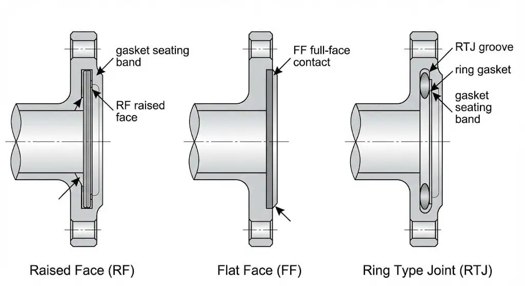
Flange facing types directly affect sealing behavior and maintenance repeatability. The three common facing types are raised face (RF), flat face (FF), and ring-type joint (RTJ). In practice, the “best” facing is the one that delivers stable gasket stress without damaging the gasket or face finish, and that you can assemble consistently in the field.
| Flange Type | Sealing Performance Characteristics |
|---|---|
| Raised Face (RF) | Common in process piping; concentrates gasket stress on the raised area. Works well with many gasket styles when assembled correctly. |
| Flat Face (FF) | Full-face contact; commonly used when mating to flanges/materials that benefit from full-face gasket support (verify compatibility—mixing FF and RF can create uneven gasket compression if not handled correctly). |
| Ring Type Joint (RTJ) | Metal ring gasket in a machined groove; used for higher-severity duties when a controlled metal-to-metal sealing system is required. Requires correct groove/ring match and careful handling to avoid damage. |
- Raised face flanges suit many piping systems and can seal reliably when gasket selection and bolt-up are controlled.
- Flat face flanges can be appropriate in lower-severity duties or specific equipment interfaces—confirm the mating conditions and gasket style.
- RTJ joints are unforgiving: ring and groove must match, faces must be protected from dents, and assembly control matters.
Tip:
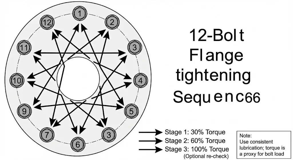
For repeatable sealing, treat assembly as part of “selection.” A controlled bolt-up approach aligned with ASME PCC-1 reduces leak recurrence by controlling gasket seating and bolt load scatter.
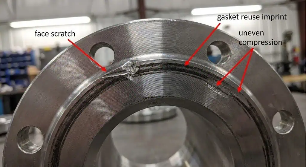
Field Example (recurring seepage after maintenance):
A common pattern is “it sealed before maintenance, then it never seals again.” The root cause is usually face damage (scratches/dings), inconsistent bolt lubrication, or reusing a gasket outside its intended service. The corrective actions are simple but strict: protect faces, replace gaskets, verify bolt material/condition, standardize lubrication, and tighten in a controlled pattern with documented steps.
Summary Table: Flange Selection Factors
| Factor | What to Check | Why It Matters |
|---|---|---|
| Pressure & Temperature | Design pressure & design temperature (including transients) | Prevents under-rating and thermal-cycle leaks |
| Media & Corrosivity | Media chemistry + contaminants + stagnation risk | Prevents localized corrosion at gasket/crevice zones |
| Facing Type | Gasket type + leakage tolerance + assembly control | Improves sealing repeatability and reduces downtime |
By carefully reviewing these factors, you make sure your flange selection matches your project’s pressure, media, and sealing needs. This step sets the stage for proper flange type selection, sizing, and documentation.
Choose Stainless Steel Flange Types
Weld Neck vs Slip-On Flanges
Direct Answer:
Weld neck flanges are typically chosen for higher mechanical demand (bending, vibration, cycling), while slip-on flanges can be acceptable for lower-demand, easier-fit utility service when permitted by project rules.
You need to understand the difference in load path and inspectability before you choose stainless steel flanges for your project. A weld neck flange uses a tapered hub and a butt-welded connection that transfers stress more gradually into the pipe, and it supports higher integrity inspection (butt weld NDE where required). A slip-on flange typically uses fillet welds and is easier to align and install, but it is generally less forgiving in high-cycle vibration or bending-sensitive locations (pump discharge, compressor piping, misaligned supports).
| Flange Type | Mechanical Behavior (relative) | Inspection / QA Practicality | Best Use Case |
|---|---|---|---|
| Weld Neck | Better for bending moments, thermal cycling, and vibration-sensitive joints due to tapered hub + butt weld load path. | Butt weld can be examined per project NDE requirements; generally preferred for higher criticality lines. | Process, higher severity, and/or cycling service where leak risk is costly. |
| Slip-On | Acceptable for lower mechanical demand; more sensitive to alignment and fillet weld quality when loads increase. | Fit-up is easier, but weld quality control and dimensional checks remain essential. | Utility/low criticality service where permitted by spec and stress demand is low. |
Tip:
If your system has vibration, frequent thermal cycles, or high bending loads, a weld neck flange usually gives a more reliable joint because it manages stress and assembly variability better. Treat flange type as a mechanical integrity choice, not a “pressure number” choice.
Field Example (vibration-driven leak):
A slip-on flange at a pump discharge developed recurring seepage despite repeated gasket replacements. The root cause was cyclic vibration plus minor misalignment, which amplified bolt load scatter and gasket stress variation. The durable fix was rework to a weld neck flange, verify support/alignment, and reassemble using a controlled bolt-up procedure.
Blind, Socket Weld, and Threaded Flanges
Direct Answer:
Blind flanges isolate pipe ends, socket weld flanges are common in small-bore piping where compactness matters, and threaded flanges allow assembly without welding—but threaded joints are typically limited to low-severity conditions where leakage risk is acceptable.
You will encounter several other flange types when you choose stainless steel flanges. Blind flanges close off the end of a pipeline or vessel and are used for isolation, testing, and maintenance access. Socket weld flanges are used on small-bore lines where a compact joint is desired; pay attention to crevice risk and cleaning requirements because socket geometry can trap residue. Threaded flanges screw onto the pipe and can be useful where welding is restricted, but thread galling and seal integrity become real concerns in stainless assemblies, especially with vibration or temperature cycling.
| Type of Flange | Applications |
|---|---|
| Blind Flanges | Isolation points for inspection, pressure testing, or future tie-ins; specify corrosion allowance and consider stagnant “dead-leg” risk behind blinds. |
| Socket Weld Flanges | Small-bore lines where compactness matters; verify cleanliness requirements and whether crevice trapping is acceptable for your media. |
| Threaded Flanges | Non-weld situations in low-severity service; avoid where vibration, cycling, or high leak consequence exists. |
Note:
When you choose stainless steel flanges, match flange type to mechanical demand, inspectability, and maintenance reality—not just ease of installation.
Application Fit and Cost Considerations
Direct Answer:
Balance first cost with the cost of leakage risk: installation time, inspection requirements, and how often the joint will be opened and reassembled.
Flange selection affects total ownership cost. A “cheaper” flange type can become expensive if it increases rework, gasket consumption, or unplanned downtime. Stainless steel generally costs more than carbon steel, but it can reduce lifecycle cost in corrosive service—if you specify the correct grade and control crevice and assembly variables.
- Cost drivers you can quantify: welding hours, NDE hold points, bolt-up time, gasket replacement intervals, and leak-related downtime.
- For high-consequence joints, “repeatable assembly” is often the best cost reduction strategy—use controlled procedures and documentation aligned with ASME PCC-1.
- If you source from Sunhy or any supplier, reduce procurement risk by standardizing your order data (NPS, class/PN, facing, bore/schedule, grade, heat treatment, bolting, gasket, and required certificates).
Callout:
Most “mystery leaks” are not mysterious: they come from a mismatch between service severity and joint design/assembly control. Budget for the joint you can assemble consistently.
Summary Table: Common Stainless Steel Flange Types
| Flange Type | Key Characteristics | Recommended Use |
|---|---|---|
| Weld Neck | Best load path for bending/vibration/cycling; butt weld supports higher integrity inspection. | Higher severity process piping and cycling service. |
| Slip-On | Easy alignment and installation; performance depends heavily on fit-up and weld quality. | Lower mechanical demand service where permitted. |
| Blind | Solid isolation; creates a stagnant zone behind the blind in many layouts. | Isolation for inspection/testing; evaluate dead-leg corrosion risk. |
| Socket Weld | Compact small-bore joint; socket geometry can trap media/residue. | Small-bore systems where crevice trapping is acceptable. |
| Threaded | No welding; thread sealing integrity is the limiting factor. | Low-severity, low vibration applications where permitted. |
By understanding flange types and how they behave in real installations, you can reduce leak risk and make selection decisions that hold up after commissioning and maintenance cycles.
Stainless Steel Grades and Material Compatibility
304 vs 316 vs Duplex Flanges
Direct Answer:
316 (with molybdenum) and duplex grades typically provide better resistance to localized corrosion than 304, especially when chlorides and elevated temperature are present.
When you choose stainless steel flanges, compare grades based on the actual corrosion mechanism you are managing: pitting/crevice, stress corrosion cracking, or general attack. 304 can be appropriate for clean, low-chloride environments, but it is often a poor choice for marine splash zones or chloride-bearing process fluids. 316/316L improves pitting resistance due to Mo. Duplex alloys (such as 2205) are often selected to improve resistance to chloride-related localized corrosion and reduce SCC risk in many applications, but fabrication controls and procurement documentation become more important.
| Stainless Steel Grade | Corrosion Resistance in Marine/Chloride Conditions (rule-of-thumb) |
|---|---|
| 304 | Higher pitting/tea-staining risk; generally avoided when chlorides + wetting are persistent. |
| 316/L | Improved vs 304 due to Mo; can still pit/crevice in warm or high-chloride conditions. |
| Duplex 2205 | Often selected for improved pitting/crevice resistance and reduced SCC susceptibility in many chloride services (confirm suitability for your chemistry and temperature). |
If your flange selection involves corrosive media, document the basis for grade choice and keep it traceable. Where the decision hinges on localized corrosion resistance, reference PREN guidance such as Nickel Institute PREN guidance rather than relying on marketing claims.
Importance of “L” Grades for Welding
Direct Answer:
“L” grades (e.g., 316L) reduce sensitization risk during welding and are commonly used when you cannot control time in the sensitization temperature range or cannot apply post-weld solution treatment.
Selecting the right flange for welded piping systems means you need to consider carbon content and exposure to sensitization temperatures. Guidance commonly notes that sensitization can occur in the approximate range of 450–850°C depending on grade and thermal history; using low-carbon (“L”) grades is a standard prevention measure in many welded fabrications. See, for example, welding-related guidance such as Nickel Institute welding guidance and stainless industry references such as sensitization avoidance notes.
- Low carbon reduces susceptibility to intergranular corrosion after welding in sensitization-prone thermal cycles.
- “L” grades are a practical choice when post-weld heat treatment is not feasible at site scale.
- For critical joints, pair “L” grades with controlled heat input and proper post-weld cleaning/passivation requirements in your project spec.
If a supplier offers dual-certified 316/316L, treat it as a documentation question: request an MTR showing the heat chemistry meets the “L” carbon limit and confirm mechanical properties align with your requirements.
ASTM and ASME Standards
Direct Answer:
You must verify that flange material and flange dimensions/ratings are specified to the correct standards for your project and region.
When you choose stainless steel flanges, dimensions and rating system come from the flange standard, while material requirements come from the material specification. For forged stainless flanges, a widely referenced material specification is ASTM A182/A182M. For ASME dimensional standards, ASME B16.5 covers common sizes (NPS 1/2 through 24) and ASME B16.47 covers large diameter flanges (NPS 26 through 60). If your project is EN/DIN based, procurement and installation should align with the EN flange standard used (for example, DIN lists EN 1092-1 scope and requirements here: DIN EN 1092-1 overview).
| Standard | Description |
|---|---|
| ASME B16.5 | Dimensions, tolerances, pressure-temperature ratings, marking, and material referencing for flanges (commonly NPS 1/2 to 24). |
| ASME B16.47 | Large-diameter steel flanges (NPS 26 to 60), including ratings, dimensions, and marking/testing requirements. |
Selecting the right flange means you avoid mismatches and ensure safe operation in your pipeline.
Flange Dimensions and Standards
Sizing and Pipe Schedule
Direct Answer:
You must match the flange NPS/DN, bore, and facing to the pipe and the joint design—then verify what the project requires for schedule alignment and welding details.
Flange sizing depends on pipe outside diameter and the flange bore configuration. For weld neck flanges, the bore and weld-end details must suit the pipe OD and wall thickness used in your line. For lap-joint configurations, the stub end governs bore and schedule fit. Even where slip-on flanges allow more clearance, fit-up and weld quality still determine reliability. If your project references ASME dimensional standards, start from B16.5/B16.47 requirements and then apply your project’s piping spec constraints.
| Pipe Schedule | Wall Thickness | Selection Impact |
|---|---|---|
| 40 | Standard | Common utility/process schedule; confirm bore and weld end match for butt-weld joints. |
| 80 | Thicker | Higher wall thickness; affects weld prep, bore fit, and may change availability/lead time. |
- Verify flange bore and weld-end details match the pipe OD and the intended joint design.
- Confirm gasket seating width and facing compatibility at the selected NPS/class.
- Where thermal expansion, vibration, or cyclic loading exists, coordinate flange choice with stress/support design.
Bolt Patterns and Standard Compatibility
Direct Answer:
You must keep the joint on one standard system (ASME class or EN PN) unless you are using a designed transition solution.
Flanges follow different standards, such as ASME class-based systems and EN/DIN PN-based systems. These standards use different bolt circle dimensions, hole counts, thicknesses, and facing conventions. If you mix standards, bolt holes may not align or gasket seating may become unreliable. Use one standard system end-to-end, or use a properly engineered transition spool designed for the mismatch.
| Standard | Measurement System | Bolt Hole Pattern | Key Risk if Mixed |
|---|---|---|---|
| ASME (Class) | Inch | Defined by size/class per ASME flange standard | Misalignment + unpredictable gasket seating stress |
| EN/DIN (PN) | Metric | Defined by DN/PN per EN flange standard | Different bolt circles/thickness/facing conventions |
Tip:
Standard mismatch is one of the fastest ways to create “it almost fits” field rework. Confirm the standard system at the P&ID/spec stage and lock it in on the BOM.
Field Example (bolt hole misalignment):
A maintenance team attempted to mate an EN PN flange to an ASME class flange using “close enough” bolts. The joint assembled with forced alignment, then leaked because gasket compression was uneven and bolt load distribution was poor. The fix was replacing the flange with the correct standard and scrapping the forced-fit assembly.
Pressure Ratings
Direct Answer:
Select the lowest class/PN that meets design pressure at design temperature with your project’s required margin, and document the basis.
Pressure ratings depend on the standard and the material group. Overspecifying class/PN increases cost and may increase bolt loads and assembly sensitivity, but underspecifying leads to leaks and rework. In ASME systems, use ASME B16.5 / ASME B16.47 rating tables; in EN/DIN systems, confirm PN pressure-temperature rules for the chosen flange material group.
| Standard | Size Range (Nominal) | Rating System |
|---|---|---|
| ASME B16.5 | NPS 1/2 to 24 | Class 150 to 2500 (temperature-dependent) |
| ASME B16.47 | NPS 26 to 60 | Class 75 to 900 (temperature-dependent) |
Common Mistakes to Avoid:
- Checking pressure rating at ambient instead of design temperature.
- Ignoring pressure surges (start-up transients, thermal expansion, water hammer).
- Mixing flange standards or facing systems without a designed transition.
- Assuming bolt torque equals bolt load (lubrication and K-factor scatter can be significant).
- Reusing gaskets or assembling without a controlled bolt-up method (pattern + staged tightening).
Note:
Careful flange sizing and rating selection improves mechanical integrity and reduces maintenance churn over the life of the piping system.
Supplier Quality and Choosing Sunhy Flanges
Quality Certifications and Testing
Direct Answer:
Verify supplier capability with certificates you can validate, material traceability you can audit, and inspection/testing aligned with your project spec.
Certifications matter only if you can verify them. Ask for certificate numbers and scope, and confirm they apply to the manufacturing site producing your flanges. For management systems, common references include ISO standards for quality, environment, and OH&S:
| Certification / Requirement | Description |
|---|---|
| ISO 9001 | Quality management system framework (verify scope + site coverage). |
| ISO 14001 | Environmental management system framework (verify scope + site coverage). |
| ISO 45001 | Occupational health and safety management system framework (replaces OHSAS 18001 in many programs). |
| PED 2014/68/EU (EU projects) | Regulatory conformity framework for pressure equipment placed on the EU market (apply when relevant). |
On the technical side, align material and heat treatment to a recognized specification such as ASTM A182/A182M when using forged stainless flanges. For stainless grades, heat treatment is not optional—confirm the required condition (solution annealed, quenched, etc.) and ensure it is reflected on the MTR and inspection records.
Flange Markings and Documentation
Direct Answer:
Request documentation that ties each flange to a heat number, material chemistry/mechanics, and the exact standard requirements for dimensions and ratings.
Proper documentation proves quality and traceability. At minimum, request Mill Test Reports (MTRs) and inspection certificates that reference your purchase requirements. If your service includes sour conditions or H2S exposure, confirm whether your project requires NACE/ISO sour service material rules, such as ISO 15156 (project requirements vary by industry and owner specifications). For EU projects, confirm PED documentation scope when applicable: Directive 2014/68/EU text.
If you are buying from Sunhy, apply the same discipline: ask for traceability, confirm standard compliance (dimensions/ratings), and keep the documents attached to the line item in your quality record package.
Global Support and Customer Service
Direct Answer:
Choose suppliers who can answer technical questions in writing, provide documentation quickly, and support nonconformance resolution without delays.
Technical support is part of risk control. Before purchasing, confirm the supplier can (1) provide the required documents (MTR, dimensional reports, PMI if specified), (2) meet the flange standard and facing requirements, and (3) respond to NCR/quality issues with a documented corrective action process. Logistics matters too: packaging must protect machined faces and maintain traceability labels through shipping and storage.
Tip:
Always verify supplier reliability by checking traceability, requesting sample documents, and confirming how flange faces are protected in transit. Face damage is a common root cause of start-up leaks.
You can make safe and reliable choices by following each step in the flange selection process.
Check pressure, temperature, and material compatibility. Confirm standards, facing, and bolt-up control. Use a short decision checklist before releasing a PO:
| Decision Point | Description |
|---|---|
| Design Conditions | Design pressure/temperature documented (including surges and cycles) and class/PN checked at design temperature. |
| Standard System | ASME class vs EN/DIN PN system locked in; no mixed bolt patterns/facing conventions. |
| Material Basis | Grade selected for corrosion mechanism; material spec defined (e.g., ASTM A182/A182M where applicable). |
| Assembly Control | Gasket + facing chosen as a system; bolt-up method controlled (reference ASME PCC-1 when appropriate). |
| Documentation | MTRs, marking, and inspection records tied to heat number and purchase requirements. |
Always double-check compatibility and standards before your final flange selection. For complex projects, keep the selection basis written and review it with piping/design/maintenance stakeholders to avoid costly rework.
FAQ
What is the difference between 304 and 316 stainless steel flanges?
316 offers improved localized corrosion resistance because it contains molybdenum (Mo).
You typically choose 316/316L when chlorides or aggressive chemicals make pitting/crevice corrosion a realistic risk. 304 can be acceptable in cleaner, low-chloride environments.
- Use 304 for benign service where chloride exposure and wetting are limited.
- Use 316/316L when you expect chlorides, cleaning chemicals, or marine-adjacent wetting.
- For higher-severity chloride service, evaluate duplex grades using documented corrosion basis (reference screening concepts such as PREN guidance).
| Grade | Best Use | Localized Corrosion Resistance (relative) |
|---|---|---|
| 304 | General piping in low-chloride environments | Moderate |
| 316 / 316L | Chemical/marine-adjacent service | Higher than 304 (Mo-bearing) |
How do I know which flange pressure rating to select?
Use design pressure and design temperature, then verify allowable rating from the governing standard tables.
Do not select class/PN using ambient ratings. In ASME systems, confirm your selection against ASME B16.5 or ASME B16.47 tables for your material group.
- Start with design P/T (include credible surges and thermal cycles).
- Confirm material group and temperature derating behavior.
- Select the lowest rating that meets requirements with the project’s required margin and documented basis.
Can I mix different flange standards like ANSI and DIN?
It is not recommended.
Mixing standard systems commonly causes bolt pattern mismatch and unreliable gasket seating. Keep one standard system end-to-end, or use a properly engineered transition solution. For reference on EN flange scope and requirements, see DIN EN 1092-1 overview.
Why do I need Mill Test Reports (MTRs) for my flanges?
MTRs prove material chemistry, mechanical properties, and traceability to a heat number.
If your purchase references a material specification such as ASTM A182/A182M, the MTR is the document that shows the delivered flange meets the specification requirements. For critical work, pair MTR review with positive material identification (PMI) when required by the project.
How can I ensure I get the right flange for my project?
Use an order checklist and an assembly checklist—then keep the records.
Before ordering, lock down the technical inputs. Before commissioning, assemble the joint using a controlled procedure (patterned tightening, verified lubrication, staged tightening), aligned with guidance such as ASME PCC-1 when applicable.
- Order checklist: NPS/DN, class/PN, facing, bore/schedule, grade (e.g., 316L vs 316), material spec (e.g., ASTM A182), heat treatment condition, bolting spec, gasket type, required documents.
- Assembly checklist: face condition, correct gasket, bolt condition and lubrication, tightening pattern + staging, leak check after thermal stabilization where allowed.


