








Guida tecnica al sensore di ossigeno
Scopri come un sensore di ossigeno segnala l'ossigeno dei gas di scarico alla centralina ECU, come differiscono i sensori a monte e a valle e cosa verificare prima della diagnosi o della sostituzione.

Risposta rapida
Un sensore di ossigeno misura l'ossigeno residuo nei gas di scarico e invia un segnale elettrico al modulo di controllo del motore. Il modulo di controllo utilizza il feedback del sensore a monte per valutare e regolare la combustione, mentre i sensori a valle sono comunemente utilizzati per monitorare le prestazioni del catalizzatore. Il sensore riporta evidenze; non aggiunge direttamente carburante, non ripara un problema di miscela né dimostra quale componente si è guastato. L'interpretazione corretta dipende dal fatto che il sensore sia a banda stretta, a banda larga/A/F o al titanio, se si trova prima o dopo il catalizzatore e se il motore ha raggiunto lo stato operativo richiesto. Prima della sostituzione, identificare il banco e la posizione esatti, ispezionare il circuito e lo scarico e confrontare i trim di carburante e la risposta in tempo reale con le informazioni di assistenza del veicolo.
Il percorso del segnale: scarico, sensore, ECU e controllo carburante
La combustione lascia una quantità variabile di ossigeno nei gas di scarico. Un sensore installato nel flusso di scarico reagisce a tale ossigeno e produce un segnale di tensione o corrente. Il modulo di controllo motore interpreta il segnale insieme a carico, temperatura, flusso d'aria, correzione del carburante e altri input. Su un motore caldo in funzionamento a ciclo chiuso, il modulo può correggere il comando dell'iniettore per mantenere la combustione vicina al suo obiettivo previsto.
Questo è un anello di retroazione, non un sistema di misurazione autonomo. Una perdita di aspirazione, una bassa pressione del carburante, un problema all'iniettore, una perdita di scarico o un guasto al cablaggio possono modificare il segnale del sensore senza che l'elemento sensibile sia la causa principale.
Cosa fanno i sensori a monte e a valle
| Posizione | Compito tipico | Limite diagnostico |
|---|---|---|
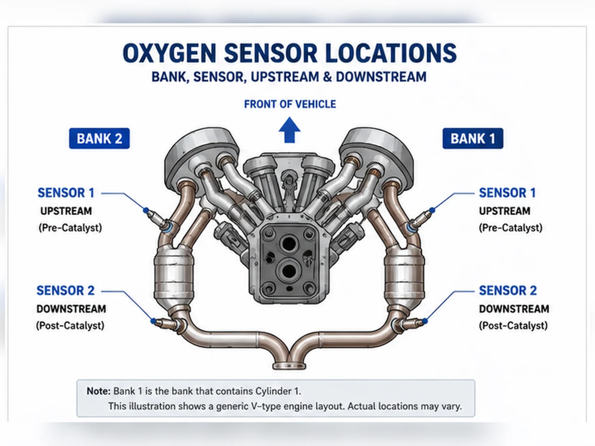
| A monte / pre-catalizzatore / solitamente Sensore 1 | Fornisce il feedback della miscela utilizzato per il controllo del carburante. | Un'indicazione di magra o ricca può essere causata dal motore, dal sistema aria/carburante, dal cablaggio o da una perdita di scarico. |
| A valle / post-catalizzatore / solitamente Sensore 2 | Aiuta il modulo di controllo a valutare le prestazioni di stoccaggio dell'ossigeno del catalizzatore. | Un codice di efficienza del catalizzatore non dimostra automaticamente che il sensore posteriore o il catalizzatore debbano essere sostituiti. |
“Solitamente” è importante. La denominazione della posizione deve essere confermata dalle informazioni di servizio del veicolo. Il Banco 1 è il banco che contiene il cilindro 1, non una regola universale lato guida o lato passeggero.
Perché la tecnologia del sensore modifica il segnale
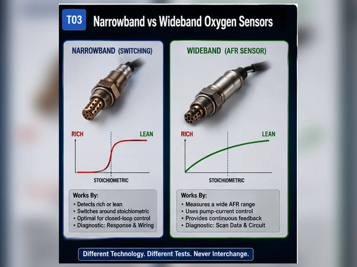
I sensori a zirconio a banda stretta vengono comunemente interpretati attorno a un punto di commutazione ricco/magro. I sensori a banda larga o del rapporto aria-carburante utilizzano un circuito di controllo più complesso e possono segnalare la deviazione della miscela su un intervallo più ampio. I progetti al titanio funzionano in modo diverso. Un grafico dello scanner diagnostico che è normale per una tecnologia può essere fuorviante per un'altra, quindi la diagnosi richiede la specifica di servizio corretta.
Cosa succede quando il segnale è errato
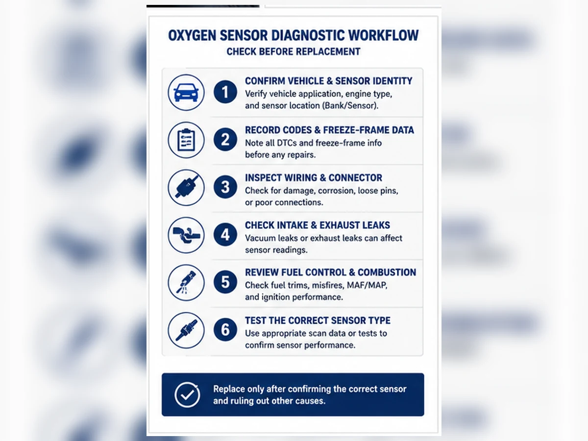
Un sensore polarizzato, lento, disconnesso o non riscaldato può contribuire a uno scarso controllo del carburante, a un aumento delle emissioni, a problemi di guidabilità o a una spia di avvertimento. Tuttavia, gli stessi sintomi possono essere prodotti da altri sistemi. Prima della sostituzione, ispezionare il cablaggio e il connettore, controllare l'alimentazione del riscaldatore e la massa quando pertinente, cercare perdite di scarico, rivedere i trim del carburante e confrontare i dati in tempo reale con la procedura diagnostica del produttore.
Cosa registrare prima dell'ordine
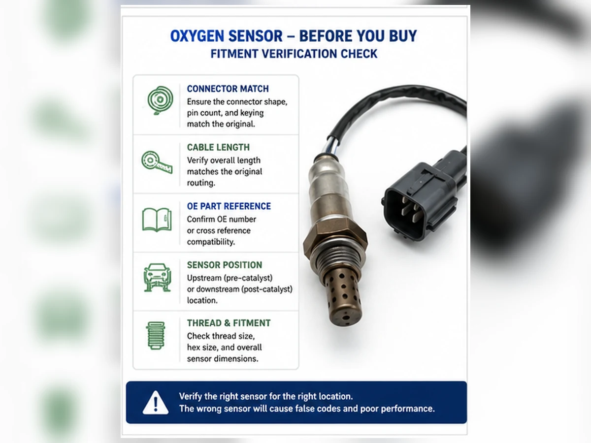
- Numero OE del pezzo rimosso o da una fonte di catalogo verificata
- Anno, marca, modello, motore e mercato
- Posizione della bancata e del sensore
- Codifica del connettore, numero di pin e lunghezza del cavo
- Tecnologia del sensore e design diretto o universale
- Risultati diagnostici rilevanti, non solo il codice di guasto
Cosa c'è all'interno di un sensore di ossigeno?
L'involucro filettato visibile è solo l'interfaccia meccanica. All'interno, l'elemento sensibile opera a temperatura elevata ed è protetto dall'impatto diretto dei gas di scarico da uno schermo. Un riscaldatore aiuta l'elemento a raggiungere e mantenere il suo intervallo operativo. I terminali elettrici trasportano i circuiti di rilevamento e riscaldamento attraverso un cavo resistente al calore fino a un connettore specifico per l'applicazione. La costruzione esatta varia a seconda del design a banda stretta, titania e banda larga.
Elemento sensibile e strategia di riferimento
Un elemento a banda stretta in zirconio sviluppa un segnale correlato alla differenza di ossigeno attraverso la ceramica. È utile intorno alla zona di commutazione ricca/magra ma non è un analizzatore di gas di scarico da laboratorio. Un sensore a banda larga aggiunge una strategia di controllo a cella di pompaggio che consente una misurazione della miscela più ampia. Il modulo di controllo e il sensore formano un sistema elettrico accoppiato; un componente a banda larga non può essere giudicato dal familiare pattern di tensione a banda stretta.
Circuito riscaldatore
Il riscaldatore riduce il tempo prima del feedback utile e aiuta a mantenere la temperatura al minimo o a basso carico. Un codice del riscaldatore può derivare da un elemento aperto, alta resistenza, un fusibile bruciato, cablaggio danneggiato, massa scarsa, resistenza del connettore o un guasto lato controllo. Misurare solo la resistenza del sensore non completa la diagnosi del circuito.
Schermo, filettatura, cavo e connettore
Lo schermo controlla l'esposizione ai gas e protegge l'elemento. Le dimensioni della filettatura e dell'esagono determinano l'installazione meccanica. La lunghezza del cavo, l'isolamento, il fissaggio e le clip tengono il cablaggio lontano dallo scarico e dai componenti in movimento. La sola forma del connettore non è sufficiente: codifica, assegnazione dei pin e caratteristiche elettriche devono corrispondere all'applicazione.
Come cambia il ruolo del sensore in base allo stato operativo
| Stato operativo | Cosa può fare il sistema di controllo | Attenzione diagnostica |
|---|---|---|
| Avviamento a freddo | Utilizzare l'alimentazione programmata mentre il sensore e il catalizzatore si riscaldano. | Un segnale a freddo non deve essere confrontato con le specifiche a caldo a ciclo chiuso. |
| Riscaldamento al minimo | Utilizzare il feedback quando le condizioni di abilitazione sono soddisfatte. | Perdite di scarico e basso flusso possono influenzare fortemente le letture. |
| Crociera stabile | Applicare la correzione a breve e lungo termine ed eseguire alcuni monitoraggi. | Carico, velocità e temperatura devono essere stabili per i confronti. |
| Accelerazione o carico elevato | Utilizzare arricchimento specifico della strategia o controllo ad anello aperto. | Può essere comandata un'indicazione di miscela ricca anziché un guasto. |
| Riduzione carburante in decelerazione | Ridurre o interrompere l'iniezione in condizioni definite. | Durante l'evento ci si può aspettare un elevato contenuto di ossigeno nello scarico. |
Ecco perché uno screenshot di un singolo valore dello strumento di scansione raramente risponde se il sensore funziona. Il tecnico ha bisogno dello stato comandato, della temperatura del motore, del carico, dei correttori di carburante, della tecnologia del sensore e della risposta prevista dal costruttore in quel test.
Come interpretare i dati del sensore di ossigeno senza fare supposizioni
Iniziare con l'etichetta dei dati e le unità di misura
Uno strumento di scansione può visualizzare tensione, corrente, lambda, rapporto di equivalenza o un valore calcolato. Confermare che l'identificatore del dato sia supportato dal veicolo e corrisponda al sensore fisico in esame. Le etichette generiche dello strumento di scansione possono semplificare i sistemi specifici del costruttore.
Confrontare la risposta, non un singolo numero
Per un sensore a banda stretta, l'osservazione utile può essere la risposta di commutazione in condizioni di caldo definite. Per un sensore a banda larga, la procedura può valutare la corrente di pompa o la risposta lambda a una variazione controllata. Confrontare il risultato con i trim del carburante e la miscela comandata. Un sensore che segnala magro mentre il trim del carburante aggiunge carburante potrebbe rivelare accuratamente un problema di aria o di alimentazione.
Utilizzare il segnale a valle nel contesto
Il sensore posteriore viene valutato insieme al sensore anteriore e alle condizioni operative del catalizzatore. Forme d'onda simili possono sollevare un problema di monitoraggio del catalizzatore, ma devono essere escluse perdite di scarico, mancate accensioni e bias del sensore. P0420 o P0430 non è un'istruzione diretta per sostituire uno dei due sensori.
Quali strumenti di test comuni possono e non possono stabilire
| Strumento o evidenza | Utile per | Limitazione importante |
|---|---|---|
| Ispezione visiva | Rilevamento di cablaggio fuso, connettori allentati, danni da impatto e perdite evidenti dello scarico | Impossibile dimostrare la risposta interna o la calibrazione. |
| Strumento di scansione | Lettura dei codici, freeze frame, correzioni carburante, stato monitor e dati sensori supportati | Le etichette e le velocità di trasmissione variano; i valori generici potrebbero non rappresentare il test del produttore. |
| Multimetro digitale | Controllo di alimentazione, massa, continuità e resistenza dove la procedura lo consente | Potrebbe non catturare il comportamento rapido del segnale e danneggiare i circuiti se usato in modo errato. |
| Oscilloscopio | Osservazione della forma d'onda, risposta e comportamento intermittente del circuito | La forma d'onda richiede ancora condizioni operative note e un'interpretazione specifica della tecnologia. |
| Prova di fumo o perdite | Individuazione di perdite di aspirazione o scarico che alterano le prove della miscela | Deve essere eseguita con attrezzatura adeguata e un metodo sicuro e appropriato per l'applicazione. |
| Informazioni di servizio | Definizione di posizione, circuito, criteri di abilitazione, dati previsti e sequenza di test | Deve corrispondere esattamente a veicolo, motore, mercato e calibrazione. |
Nessun singolo strumento sostituisce la catena di prove. Un multimetro può mostrare che un circuito del riscaldatore è aperto ma non spiegare perché è stato memorizzato un codice di miscela. Un grafico di scansione può mostrare un segnale piatto ma non distinguere un sensore guasto da un'alimentazione mancante, un identificatore di dati non supportato o un motore che non è entrato nello stato di test richiesto. Combina il risultato dello strumento con lo schema elettrico e le condizioni operative.
Guasto del sensore o guasto del sistema? Utilizzare una modifica controllata
Un test diagnostico utile modifica una condizione nota e osserva se il valore riportato risponde nella direzione e nei tempi previsti. Il metodo esatto deve provenire dalle informazioni di servizio; creare deliberatamente condizioni di miscela ricca o magra non sicure non è appropriato. Il ragionamento è ciò che conta: se altri dati confermano che la miscela è cambiata e il sensore non ha risposto, il sospetto si sposta verso il sensore o il circuito. Se il sensore risponde ma i trim di carburante rimangono anomali, continuare a indagare sul sistema aria, carburante, accensione o meccanico.
Verificare anche se il guasto segue un movimento del cablaggio, una variazione di temperatura o un disturbo del connettore. Aperture intermittenti vicino allo scarico caldo possono apparire solo dopo l'espansione. Documentare il percorso originale prima della riparazione e ripristinare ogni schermo termico e clip. Un sensore corretto collegato attraverso un cablaggio danneggiato non può svolgere la sua funzione in modo affidabile.
Perché i sensori di ossigeno diventano lenti, sbilanciati o danneggiati
| Meccanismo | Possibili prove | Prossimo passo corretto |
|---|---|---|
| Invecchiamento termico | Risposta più lenta dopo esposizione prolungata al calore | Verificare la risposta utilizzando il test specificato prima della sostituzione. |
| Contaminazione da olio o refrigerante | Depositi più sintomi del sistema di raffreddamento o consumo | Correggere la perdita del motore; un nuovo sensore da solo potrebbe guastarsi di nuovo. |
| Avvelenamento da silicone o sostanze chimiche | Inceppamento persistente o depositi legati a sigillanti/fluidi non idonei | Rimuovere la fonte di contaminazione e seguire i materiali approvati. |
| Urto o manipolazione impropria | Schermo, ceramica o cavo danneggiati | Sostituire la parte danneggiata e correggere la pratica di installazione. |
| Danneggiamento termico del cablaggio | Isolamento fuso, segnale intermittente o codice riscaldatore | Riparare il percorso e l'integrità del circuito, non solo il sensore. |
| Perdita di scarico | L'aria esterna modifica la lettura vicino al sensore | Riparare la perdita prima di valutare la risposta del sensore. |
Scenario diagnostico composito: quando un segnale magro è corretto
Scenario di ingegneria composita: Un motore caldo imposta un codice magro e il sensore a monte rimane magro mentre il trim del carburante aumenta. Sostituire il sensore sarebbe allettante. Un test al fumo invece trova una perdita di aspirazione a valle della misurazione del flusso d'aria. Dopo aver riparato la perdita, il trim del carburante ritorna verso l'intervallo previsto del veicolo e il sensore risponde normalmente.
Questo scenario combina una logica diagnostica comune e non rappresenta un cliente, veicolo o risultato di test di Sunhyings. Il suo scopo è mostrare la funzione effettiva del sensore: può essere il messaggero piuttosto che la causa.
Cosa un sensore di ossigeno non può dirvi da solo
- Non può identificare quale iniettore, guarnizione o componente di accensione ha causato la condizione di scarico.
- Non può provare la condizione del catalizzatore da una singola lettura stazionaria.
- Non è possibile stabilire l'adattamento del veicolo dall'aspetto della filettatura o del connettore.
- Non è in grado di distinguere ogni fonte di contaminazione senza prove fisiche e di sistema.
- Non può rendere un bypass delle emissioni una riparazione legale o efficace.
Il passo successivo corretto dipende dall'attività dell'utente. Per la diagnosi, seguire il percorso di test del codice di guasto e dei dati in tempo reale. Per la sostituzione, utilizzare la procedura del veicolo e le pratiche sicure per il sistema di scarico. Per l'acquisto, creare un record completo OE/YMME/posizione prima di confrontare fornitori o prezzi.
Limite di sicurezza e conformità dopo la diagnosi
Se i test supportano la rimozione, lasciare raffreddare lo scarico e utilizzare attrezzature approvate per il sollevamento e il supporto del veicolo. Instradare il cablaggio lontano da calore, bordi taglienti e parti in movimento, e ripristinare ogni clip e schermo termico. Utilizzare le istruzioni di coppia e antigrippaggio del fornitore del veicolo o del sensore invece di un valore universale. Non tagliare un cablaggio direct-fit; un design universale con giunzione deve essere elencato per l'applicazione e installato secondo la procedura del produttore.
Dopo la riparazione, verificare la risposta del circuito e del sensore nelle condizioni richieste e consentire il completamento del monitor di prontezza applicabile. Cancellare un codice non prova la riparazione. Un distanziale, simulatore, eliminazione del sensore o sconfitta software non può sostituire una diagnosi legale e potrebbe violare le normative sulle emissioni.
Tabella decisionale funzione-azione
| Osservazione dell'utente | Cosa suggerisce la funzione del sensore | Azione prima dell'ordine |
|---|---|---|
| Miscela magra e trim carburante positivo | Il sensore potrebbe segnalare un reale eccesso di ossigeno. | Controllare perdite di aspirazione/scarico, erogazione carburante e dati del flusso d'aria. |
| Codice riscaldatore | L'elemento potrebbe non raggiungere la temperatura di esercizio prevista. | Testare fusibile, alimentazione, massa, controllo, connettore e resistenza del riscaldatore. |
| Codice risposta lenta | Il segnale non è cambiato entro i criteri del monitor. | Verificare le condizioni operative, perdite, controllo della miscela e tecnologia del sensore. |
| Codice di efficienza del catalizzatore | Il monitor ha rilevato un problema di relazione a monte/valle. | Controllare insieme le evidenze di motore, scarico, sensore e catalizzatore. |
| Una diagnosi corretta supporta la sostituzione | Il sensore o il cablaggio integrato non può soddisfare la sua funzione richiesta. | Verificare il riferimento OE, la posizione esatta, la tecnologia e l'interfaccia fisica. |
Cosa misura il sensore e cosa deduce la centralina
Un sensore di ossigeno automobilistico risponde alle condizioni relative all'ossigeno nei gas di scarico. Il modulo di controllo interpreta il suo comportamento di tensione, resistenza o corrente di pompaggio in base al progetto del sensore. Non è una sonda percentuale di ossigeno da laboratorio e non misura in modo indipendente il flusso di carburante, la conversione del catalizzatore o la qualità della combustione. Queste conclusioni derivano da un modello che combina il sensore con altre evidenze del motore e dello scarico.
| Livello del segnale | Cosa rappresenta | Cosa non può stabilire da sola |
|---|---|---|
| Risposta dell'elemento sensibile | Reazione specifica della tecnologia alle condizioni di ossigeno nei gas di scarico | Quale componente del motore ha causato la miscela |
| Comportamento del riscaldatore | Capacità di raggiungere/mantenere la temperatura di esercizio | Precisione del segnale del sensore in ogni condizione |
| Parametro dati ECU | Valore grezzo o derivato selezionato dalla calibrazione/strumento | Interpretazione universale di tensione/corrente |
| Regolazione del carburante | Risposta di correzione del controllore nelle regioni operative | Guasto del sensore senza contesto aria/carburante/scarico |
| Risultato del monitoraggio del catalizzatore | Valutazione calibrata utilizzando il comportamento a monte/valle | Sostituzione automatica del sensore posteriore o del catalizzatore |
Tre famiglie tecnologiche richiedono modelli mentali diversi
| Tecnologia | Concetto operativo generale | Rappresentazione diagnostica comune | Avviso di selezione |
|---|---|---|---|
| Zirconia a banda stretta | Transizione forte intorno a una regione di controllo ricco/magro | Commutazione di tensione a caldo e controllato | Non è un misuratore AFR preciso a gamma ampia |
| Titania | Il comportamento della resistenza cambia con le condizioni di scarico | Circuito/valore specifico del produttore | Non applicare presupposti di zirconio |
| Ampia gamma/A/F | Il circuito di comando aziona la cella della pompa per bilanciare la camera di misura | Corrente, lambda, rapporto di equivalenza o valore A/F derivato | Il controller, il sensore e la calibrazione devono corrispondere |
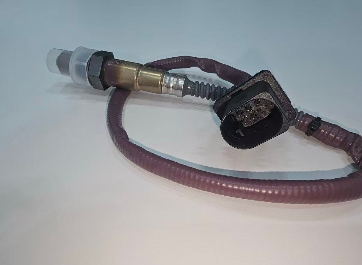
Il numero di fili o pin può essere un indizio ma non è una specifica tecnica. Gli strumenti di scansione rinomino o ridimensionano anche i dati. Utilizzare sempre le informazioni esatte del veicolo e le specifiche del prodotto prima di interpretare o sostituire un sensore.
Il ciclo di controllo cambia al variare dello stato del motore
| Stato | Possibile strategia di controllo | Avvertenza sull'interpretazione del sensore |
|---|---|---|
| Avviamento a freddo | Alimentazione programmata / a ciclo aperto mentre i sensori / catalizzatore si riscaldano | L'inattività a freddo non viene giudicata con criteri a caldo |
| Riscaldamento al minimo | Correzione a ciclo chiuso quando abilitato | Portate basse e piccole perdite di scarico possono influenzare le letture |
| Crociera stabile | Feedback e alcune attività di monitoraggio | Carico/temperatura stabili sono necessari per il confronto |
| Accelerazione/carico elevato | Arricchimento specifico della strategia o anello aperto | Può essere comandato un comportamento ricco |
| Riduzione carburante in decelerazione | Carburante ridotto/interrotto in condizioni definite | È possibile un elevato contenuto di ossigeno nello scarico |
| Ripiego in caso di guasto | Valori sostitutivi o controllo alternativo come calibrato | Nessun effetto universale sul consumo di carburante o sulla guidabilità |
Come le informazioni a valle supportano il monitoraggio del catalizzatore
Un catalizzatore immagazzina e rilascia ossigeno al variare della composizione dei gas di scarico. Il modulo di controllo può confrontare il comportamento prima e dopo il catalizzatore durante condizioni di abilitazione definite. Un sistema sano spesso modifica il pattern a valle rispetto al comportamento a monte, ma non esiste una tensione fissa universale che dimostri la salute del catalizzatore. La calibrazione del monitor, la tecnologia del sensore, le perdite, i misfire e il controllo della miscela sono tutti importanti.
P0420/P0430 significa che il monitor dell'efficienza del catalizzatore ha valutato al di sotto della sua soglia calibrata per una bancata. Non dice “sostituire il sensore 2”. Validare il controllo a monte, il circuito a valle, la tenuta dello scarico, i guasti del motore e la contaminazione prima di seguire l'esatto percorso diagnostico del catalizzatore.
Cosa può interferire con il lavoro del sensore?
| Percorso di guasto | Effetto sulla funzione | Evidenza prima della sostituzione |
|---|---|---|
| Circuito aperto/corto/resistenza elevata | Comportamento del segnale/riscaldatore mancante o implausibile | Test dello schema, dei terminali e del circuito sotto carico |
| Guasto del riscaldatore | Funzionamento ritardato o perso con calore di scarico basso | Alimentazione, controllo/massa e resistenza/corrente specificata |
| Perdita di scarico | Condizione segnalata di ossigeno esterno modificata | Ispezione perdite a temperatura/carico pertinente |
| Contaminazione | Risposta dell'elemento polarizzata o lenta | Test di risposta corretto per diagnosi di origine e tecnologia |
| Parte/posizione errata | Disallineamento elettrico o di calibrazione | Registrazione OE/applicazione, tecnologia e interfaccia |
| Calore/abrasione del cablaggio | Problema di circuito intermittente o permanente | Ispezione completa del percorso e del movimento |
Caso composito: il sensore funziona correttamente durante un'anomalia di magra
Scenario diagnostico composito: Un sensore a monte segnala magra e la correzione del carburante aumenta al minimo. Il segnale risponde a una modifica approvata della miscela ed entrambe le banche mostrano un pattern simile. Viene identificata e riparata una perdita di aspirazione; i sensori rimangono in servizio.
Il caso dimostra il vero compito del sensore: segnalare prove di scarico. La segnalazione accurata di un guasto non è un guasto del sensore. È composito, non un caso cliente Sunhyings.
Caso composito: un elemento buono non può funzionare senza alimentazione del riscaldatore
Scenario del reparto compositi: un sensore mostra attività ritardata e un DTC del riscaldatore. La resistenza dell'elemento è plausibile, ma un test sotto carico non rileva alimentazione dal lato veicolo a causa di un circuito condiviso danneggiato. La riparazione ripristina il riscaldamento e il funzionamento del monitor senza sostituire il sensore.
Il caso separa l'elemento sensibile dal circuito completo del sensore. Non sostiene che ogni codice del riscaldatore sia correlato al cablaggio.
Registro delle evidenze per una decisione sulla funzione del sensore
- Veicolo esatto, motore, configurazione delle emissioni e posizione Banca/Sensore
- Tecnologia del sensore e parametri di scansione supportati
- Codici, stato, freeze frame, prontezza e condizioni operative
- Risultati del test del riscaldatore e del circuito di segnale/riferimento sotto carico
- Contesto di perdite di scarico, correzione del carburante, flusso d'aria/carburante e mancate accensioni
- Stimolo, risposta, unità, scala temporale e fonte di specifica definiti
- Risultati prima/dopo e completamento del monitor legale applicabile
Limiti stechiometrici, lambda e tipo di carburante
Lambda descrive la relazione effettiva aria-carburante rispetto al riferimento stechiometrico per il carburante. Lambda 1 rappresenta tale riferimento, mentre un numero di rapporto aria-carburante per benzina dipende dalla composizione del carburante assunta. Il contenuto di etanolo e la formulazione del carburante possono modificare il valore AFR corrispondente a lambda 1. Questo è un altro motivo per cui un numero generico visualizzato sul display deve essere interpretato nel contesto del veicolo e del carburante.
| Concetto | Significato utile | Errore comune |
|---|---|---|
| Lambda | Miscela rispetto al riferimento stechiometrico | Trattandolo come percentuale di ossigeno |
| Display AFR | Rappresentazione strumento/calibrazione con assunzione di carburante | Assumendo che un unico valore per benzina si applichi a ogni carburante |
| Commutazione a banda stretta | Retroazione attorno alla regione di controllo | Lettura dell'esatta entità ricca/magra dalla tensione |
| Corrente della pompa a banda larga | Risposta controllata su un intervallo di miscela più ampio | Applicazione delle aspettative di tensione a banda stretta |
| Regolazione del carburante | Correzione del controller entro regioni definite | Chiamando la correzione il comando diretto del carburante del sensore |
Gli strumenti osservano diversi livelli della funzione
| Strumento o registro | Domanda a cui può rispondere | Limite |
|---|---|---|
| Strumento di scansione | Quale parametro e risultato del monitor riporta la ECU | Può filtrare, scalare o non supportare i dati necessari |
| Misuratore digitale | Tensione/resistenza/continuità secondo metodo definito | Può non rilevare il comportamento di carico o temporizzazione |
| Misuratore grafico/oscilloscopio | Forma d'onda, risposta ed eventi intermittenti | Richiede circuito corretto, scala e sondaggio sicuro |
| Analizzatore di gas di scarico | Evidenza indipendente del gas in condizioni di prova | Non identifica il montaggio o ogni causa principale |
| Metodo fumo/perdita | Potenziale perdita di aspirazione/scarico | Deve essere compatibile con sistema, temperatura e limiti di sicurezza |
| Informazioni di servizio | Pinout, dati previsti, criteri di abilitazione e procedura | Deve corrispondere esattamente a veicolo/configurazione |
Un risultato dello strumento è credibile solo con unità di misura, condizioni operative, identità del canale e fonte della specifica. Non applicare tensione esterna né sondare un circuito a banda larga a meno che la procedura non lo consenta esplicitamente.
Come una funzione diventa una specifica di sostituzione
Una volta che i test supportano la sostituzione, tradurre il requisito funzionale in identità esatta del pezzo. Corrispondenza con OE/applicazione, posizione Banco/Sensore, tecnologia, comportamento riscaldatore/elettrico, connettore e mappa terminali, percorso cavo/fascetta, filettatura e schermatura. Un sensore che si avvita fisicamente ma invia il tipo di segnale sbagliato non può svolgere la funzione richiesta.
Sunhyings può esaminare le prove di montaggio e approvvigionamento presentate. Le foto reali dei prodotti in questa pagina mostrano solo esempi fisici; non stabiliscono numero OE, compatibilità con il marchio, disponibilità a magazzino o certificazione senza una registrazione confermata a livello di componente.
Il sensore supporta il controllo delle emissioni; non è un obiettivo di bypass
Simulatori, distanziatori, eliminazioni di sensori e dispositivi di bypass del monitoraggio software non riproducono un rilevamento e una diagnosi legali. Possono nascondere prove del catalizzatore o della miscela e violare le normative sulle emissioni. Ripristinare il sensore, il catalizzatore e il sistema di controllo progettati e verificare il monitor applicabile. Nessun sensore può garantire che ogni veicolo superi un'ispezione senza una diagnosi completa del veicolo.
Per i veicoli statunitensi, le normative EPA/CARB e le informazioni di servizio applicabili controllano i lavori sulle emissioni; altri mercati richiedono una revisione normativa locale. Il ruolo legittimo del sensore è la misurazione e il feedback. Modificarne la posizione o il segnale per manipolare un monitor rompe il rapporto tra le prove di scarico e l'interpretazione dell'ECU, invece di riparare il sistema.
Quando la sostituzione è giustificata, mantenere la posizione progettata e il percorso di montaggio diretto, quindi verificare la stessa questione funzionale che ha causato il guasto prima della riparazione. Questo chiude il ciclo dal componente fisico al risultato legale del monitor.
Per l'approvvigionamento, richiedere prove che il sensore proposto possa eseguire la funzione esatta nella posizione indicata: tecnologia, specifica del riscaldatore/elettrica, connettore, cavo, filettatura, schermatura, mappatura delle applicazioni, validazione e tracciabilità. Una fotografia del prodotto può confermare solo la costruzione visibile; non può confermare la calibrazione o la copertura del veicolo.
Durante una richiesta di garanzia, testare lo stesso livello funzionale contestato. Un reclamo sul riscaldatore richiede prove del circuito e del riscaldatore; un reclamo sulla risposta richiede condizioni operative valide e dati corretti dal punto di vista tecnologico; un reclamo di montaggio errato richiede registrazioni del veicolo, della posizione e dell'interfaccia. Non utilizzare un test banale generico per rispondere a una domanda di campo diversa.
Prepara una richiesta di adattamento o approvvigionamento
Invia il numero OE, anno/marca/modello, motore o dettagli VIN, mercato e pacchetto emissioni, posizione esatta di banco/sensore, connettore e foto del vecchio componente, quantità e eventuali requisiti di imballaggio o approvazione. Sunhyings esaminerà i dati forniti per verificarne la capacità e la fattibilità dell'approvvigionamento; l'adattamento non è confermato fino a quando le prove di applicazione non vengono abbinate.
Domande frequenti
Un sensore di ossigeno controlla direttamente il carburante?
No. Invia un segnale al modulo di controllo del motore, che decide se e come regolare il comando dell'iniettore utilizzando più ingressi.
Ogni sensore di ossigeno svolge la stessa funzione?
I sensori a monte supportano principalmente il feedback della miscela, mentre quelli a valle supportano comunemente il monitoraggio del catalizzatore. Anche la tecnologia e la strategia del veicolo differiscono.
Un buon sensore di ossigeno può segnalare una condizione di magra?
Sì. Perdite di aspirazione, bassa erogazione di carburante, perdite di scarico e altri guasti possono creare un segnale di scarico effettivamente magro.
Un sensore O2 è uguale a un sensore di ossigeno?
Sì. Il sensore O2 è il nome abbreviato comune, sebbene i sensori di rapporto aria-carburante e a banda larga possano utilizzare strategie di segnale diverse.
Il codice P0420 indica un guasto del sensore di ossigeno?
Il codice P0420 riguarda l'efficienza del sistema catalizzatore. I dati del sensore fanno parte della diagnosi, ma il codice non identifica da solo un sensore di ossigeno guasto.
Quali informazioni sono necessarie per selezionare un ricambio?
Verificare il riferimento OE, il veicolo e il motore, il mercato o il pacchetto emissioni, la bancata e la posizione esatte, il connettore, la lunghezza del cavo e la tecnologia del sensore.